Helical Piles
Example 1
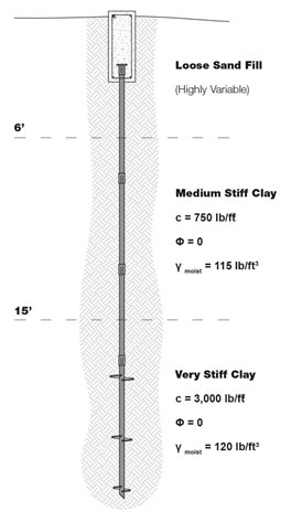
Helical piles are proposed to support a new structure. The proposed pile layout is shown on the foundation plan along with a design working load of 30 kips per pile with a Factor of Safety (FOS) = 2. Preliminary product selection suggests that the Model HP288 helical pile is the best fit for this load condition with an ultimate torque-rated capacity of 71.1 kips. The allowable torque-rated capacity would then be 35.5 kips with a FOS = 2. A geotechnical investigation was completed for the project and the soil profile is shown in the figure on the right.
The helical piles will penetrate the upper fill and medium stiff clay to bear within the deeper, very stiff clay. With the helix plates bearing entirely within the very stiff clay soil below a depth of 15 feet, we can use a simplified version of the Individual Bearing Method equation for purely cohesive soils with ф = 0.
Refer to the Technical Manual for a description of the Individual Bearing Method:
Qu = ΣAh(9c)
Solve for the required helix plate area:Ah = Qu/9c
Qu = Design Working Load (30,000 lb) x FOS (2) = 60,000 lb
c = 3,000 lb/ft2
Ah = 60,000 / (9)(3,000)
Ah = 2.22 ft2
Helix plate areas for the various shaft sizes can be found in the Technical Manual. For the Model HP288 (2.875-inch O.D.), a total helix plate area of 2.22 ft2 can be most effectively achieved with a 10/12/14 triple-helix plate configuration.
A10" = 0.50 ft2
A12" = 0.74 ft2
A14" = 1.02 ft2
---------------------------------
∑Ah = 2.26 ft2
Solve for the ultimate and allowable pile capacities:
Qu = (2.26)(9)(3,000) = 61,020 lb = 61 kips
The allowable pile capacity:
Qa = Qu / FOS
Qa = 61 / 2 = 30.5 kips.....OK
Determine the required final installation torque in accordance with the equation from the Torque Correlation Method:
Qu = KtT
This equation can be solved for torque:
T = Qu / Kt
Without a site-specific load test and determination of Kt, we use the default value from ICC-ES AC358 for a 2.875-inch O.D. shaft, Kt = 9 ft-1.
T = 60,000 / 9 = 6,667 ft-lb
Install the helical piles to a final installation torque of at least 6,700 ft-lb.
Example 2
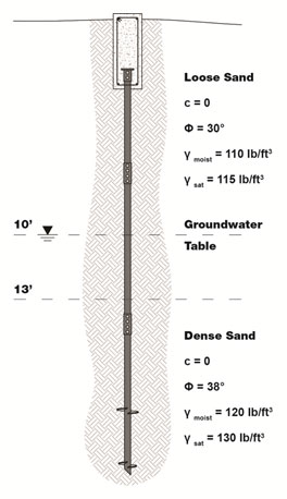
Grain conveyor towers will be constructed at an ethanol facility. The towers will be designed with four support legs, each leg designed for working loads of 40 kips in compression and 15 kips in tension/uplift. A Factor of Safety (FOS) = 2 is required for both the compression and uplift pile capacities. Preliminary product selection suggests that the Model HP350 helical pile is best suited to support the proposed loads. The HP350 has an ultimate torque-rated capacity of 122.5 kips and an allowable capacity of 60 kips, limited by ICC-ES AC358. The helical piles will be embedded into the dense sand as shown in the figure to the right.
For purely granular (frictional) soils with c = 0, the ultimate pile capacity can be determined from equation:
Qu = ΣAh(q'Nq)
Solve for the required helix plate area:
Ah = Qu / q'Nq
The helix plates should be embedded several plate diameters into the dense sand to provide uplift resistance. This depth depends both on soil conditions and pile load. We can fine tune the embedment depth at a later point, but for an uplift load of 15 kips, we'll consider a helix plate embedment of three diameters into the dense sand, as measured to the uppermost plate. A pile with an ultimate capacity of 80 kips often has three helix plates on the lead section. A 10/12/14 lead has a distance of 5.5 feet between the uppermost and bottommost plates. In granular soils helical pile capacity is dependent on effective overburden pressure. With these parameters in mind, we'll choose a trial "average" effective overburden depth of:
13 feet + 3.5 feet (depth of 14-inch plate into dense sand) + 2.75 feet (half the distance between bearing plates) = 19.3 feet.
The 14-inch diameter helix plate is located at a depth of 16.5 feet. ICC-ES AC358 established torque correlation factors under tension loading at depths of 12 plate diameters or more from the ground surface. The 14-inch plate should therefore be located at a depth of at least 14 feet. That criteria is met in this example. The design professional shall select an appropriate embedment depth and torque correlation factor when the 12D criteria is not met.
The vertical effective overburden stress, q', at 19.3 feet:
q' = (110 lb/ft3)(10 ft) + ((115-62.4) lb/ft3)(3 ft) + ((130-62.4) lb/ft3)(6.3 ft) = 1,683 lb/ft2
Qu = Design Working Compression Load (40,000 lb) x FOS (2) = 80,000 lb
Nq = 1+0.56(12ф)ф/54 = 42.6 (for ф = 38°)
Ah = 80,000 / (1,683)(42.6)
Ah = 1.11 ft2
For the HP350 shaft (3.5-inch O.D.), a total helix plate area of at least 1.11 ft2 can be achieved with a 10/12 double-helix plate configuration.
A10" = 0.48 ft2
A12" = 0.72 ft2
---------------------------------
ΣAh = 1.20 ft2
To maintain the average vertical effective overburden stress at a depth of 19.3 feet, the 12-inch blade would need to be installed to a depth of roughly 18.0 feet and the 10-inch blade would be installed to a depth of 20.5 feet. The upper helix plate is now 5.0 feet below the loose sand to dense sand interface. With this depth of embedment, we would expect the allowable uplift capacity to be similar to the allowable compressive capacity.
The vertical effective overburden stress, q'12", at 18.0 feet:
q'12" = (110 lb/ft3)(10 ft) + ((115-62.4) lb/ft3)(3 ft) + ((130-62.4) lb/ft3)(5.0 ft) = 1,595 lb/ft2
The vertical effective overburden stress, q'10", at 20 feet (limited by the Critical Depth):
q'10" = (110 lb/ft3)(10 ft) + ((115-62.4) lb/ft3)(3 ft) + ((130-62.4) lb/ft3)(7 ft) = 1,731 lb/ft2
The vertical effective overburden pressure in granular soil is limited by the Critical Depth. See the Technical Manual for further discussion. A value of 20 feet is often used as a conservative estimate.
Solve for the ultimate and allowable pile capacities:
Qu = ΣAh(q'Nq)
Qu = (0.72)(1,595)(42.6) + (0.48)(1,731)(42.6) = 84,310 lb = 84.3 kips
The allowable pile capacity:
Qa = Qu / FOS
Qa, compression = 84.3 / 2 = 42.1 kips.....OK
Again, with this depth of embedment, we would expect the allowable uplift capacity to be similar to the allowable compressive capacity.
To be very conservative and consider that the loose sand above the 12-inch plate could have some effect on the uplift capacity, we could model the soil strength (friction angle) above the 12-inch plate to represent the loose sand.
Qu = ΣAh(q'Nq)
q'12" = 1,595 lb/ft2
q'10" = 1,731 lb/ft2
Nq, 12" = 15.7 (for ф = 30°)
Nq, 10" = 42.6 (for ф = 38°)
Qu = (0.72)(1,595)(15.7) + (0.48)(1,731)(42.6) = 53,420 lb = 53.4 kips
Qa, tension = 53.4 / 2 = 26.7 kips.....OK
Determine the required final installation torque in accordance with the equation from the Torque Correlation Method:
Qu = KtT
This equation can be solved for torque:
T = Qu / Kt
Without a site-specific load test and determination of Kt, we use the default value from ICC-ES AC358 for a 3.5-inch O.D. shaft, Kt = 7 ft-1.
T = 80,000 / 7 = 11,428 ft-lb
Install the helical piles to a final installation torque of at least 11,500 ft-lb.