


 107 / 365

© 2014 Foundation Supportworks
®
,
Inc.
All Rights Reserved
p 107
APPENDIX 2A
HELICAL PRODUCT RATINGS, PROPERTIES AND DETAILS
Chapter 2
Helical Foundation Systems
Plain
Plain
Corroded
(1)
Galvanized
Corroded
(1,2)
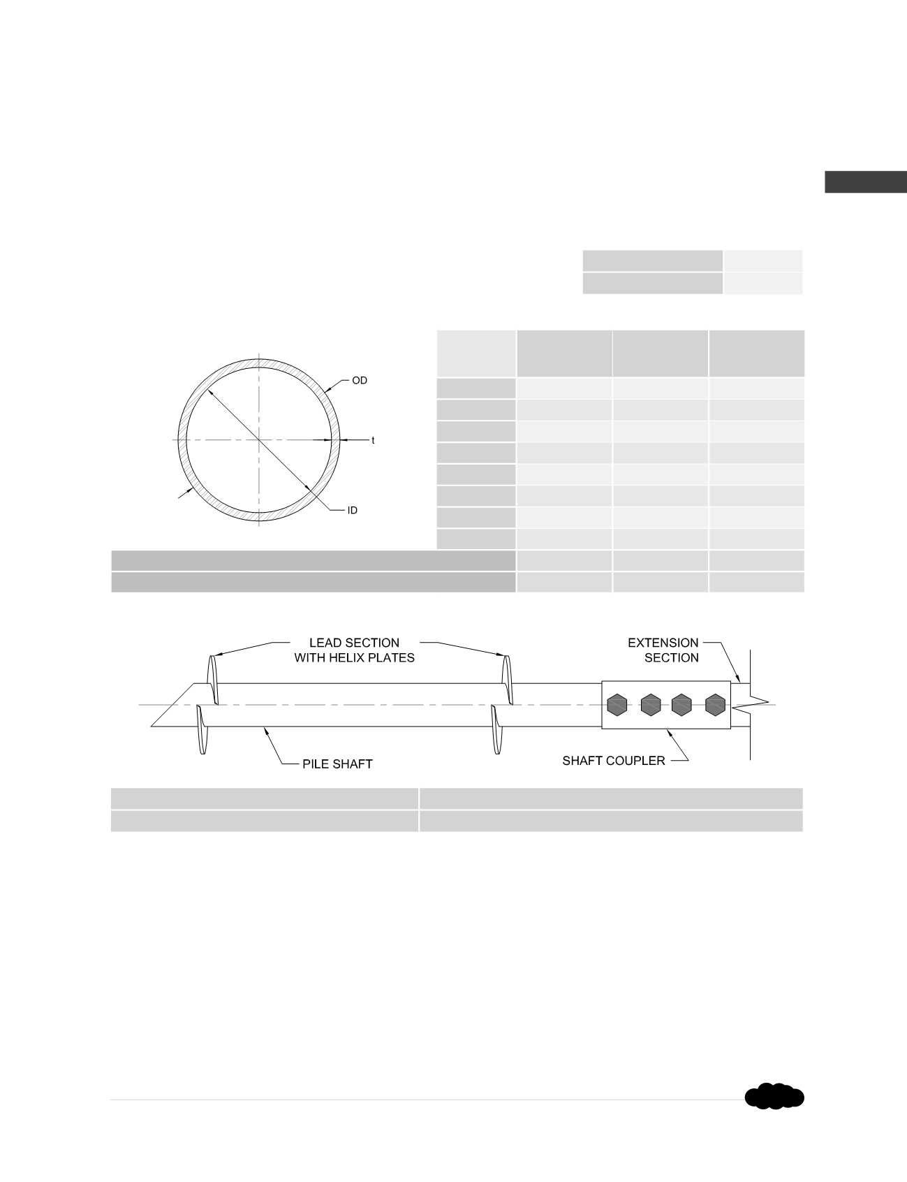
OD (in)
7.000
6.964
6.990
t (in)
0.337
0.301
0.327
ID (in)
6.326
6.362
6.336
A (in
2
)
7.05
6.30
6.84
I (in
4
)
39.25
35.04
38.08
S (in
3
)
11.21
10.06
10.89
Z (in
3
)
14.97
13.37
14.53
r (in)
2.36
2.36
2.36
Shaft Max Allowable Compression Capacity
(4,5)
P
n
/Ω (kips)
246.9
220.5
239.6
Shaft Max Allowable Tension Capacity
(5)
P
n
/Ω (kips)
135.0
118.8
130.5
HP700 Shaft Specifications and Capacities
Shaft Material
(6)
:
Ø
7.000” x 0.362” wall
ASTM A252 Grade 3
Yield strength = 60 ksi (min)
Tensile strength = 70 ksi (min)
Shaft Coupler Material
(6)
:
Ø
7.750” x 0.313” wall
ASTM A513 Type 5 Grade 1026
Yield strength = 70 ksi (min)
Tensile strength = 80 ksi (min)
Helix Plates
(6)
:
ASTM A572 Grade 50 material
1
” thick (standard)
Helix plate geometry conforming to
ICC-ES AC358
Shaft Coupling Hardware
(6)
:
(4) -
Ø
2” ASTM A307 bolts with nuts
Electrozinc plated per ASTM B633
Surface Finish of Shaft
Segments:
Available plain or hot-dip galvanized
(2)
Nominal Thickness
0.362 (in)
Design Thickness
(3)
0.337 (in)
Torque Correlation Factor
(6)
K
t
= N/A (ft
-1
)
Maximum Ultimate Soil Capacity
(6)
Q
u
= N/A (kips)
Maximum Installation Torque
(6)
T = 50,000 (ft-lb)
Maximum Allowable Soil Capacity
(6)
Q
a
= N/A (kips)
(1)
Corroded properties and capacities include a 50-year scheduled sacrificial loss in thickness per ICC-ES AC358.
(2)
Hot-dip galvanized coating in accordance with ASTM A123.
(3)
Design thickness for HSS and Pipe based on 93% of nominal thickness per AISC.
(4)
Allowable mechanical compression capacities consider continuous lateral soil confinement in soils with SPT blow counts ≥ 4. Piles with
exposed unbraced lengths or piles placed in weaker or fluid soils should be evaluated on a case by case basis by the project engineer.
(5)
Listed mechanical capacities are for the shaft and coupled connections only. System capacity should also not exceed the installed allowable
soil capacity or the allowable capacity of the respective bracket (see additional bracket tables).
(6)
FSI’s larger diameter product lines are fully customized on a project specific basis. All values provided for these products are for general
informational purposes only. Actual capacities (including any related to installation torque) will vary based on several project specific variables
such as coupler details, end termination details, site specific soil profiles, and even material availability. Full scale load tests are recommended
to confirm soil capacities determined in the design phase of the project.
Rev. 8/21/14