


 103 / 365

© 2014 Foundation Supportworks
®
,
Inc.
All Rights Reserved
p 103
APPENDIX 2A
HELICAL PRODUCT RATINGS, PROPERTIES AND DETAILS
Chapter 2
Helical Foundation Systems
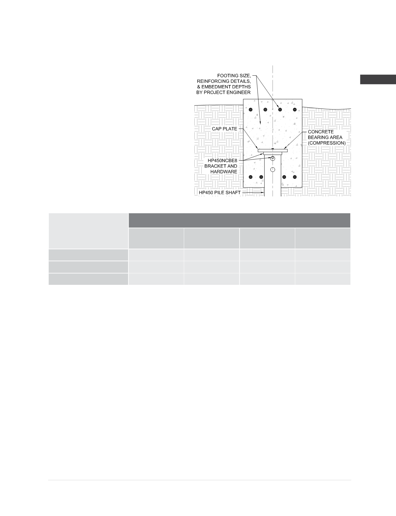
HP450NCBE8 Bracket Specifications and Capacities
when used with the HP450 Helical Pile System
Cap Plate Material:
3/4
” x 8.00” square
ASTM A36
Bracket Hardware
(5)
:
1
” square bar stock with tapped
hole and
Ø
1
” retention bolt
Bracket Finish:
Available plain or hot-dip galvanized
(2)
Concrete Bearing Area
(6)
(Compression) = 64.0 in
2
Concrete Bearing Area
(6)
(Tension) = N/A
Allowable Bracket Capacity
(4)
R
n
/Ω
Compression
(3)
(kips)
Concrete Bearing
(6)
(ksi)
Tension
(kips)
Concrete Bearing
(6)
(ksi)
Plain
80.4
1.26
0
0
Plain Corroded
(1)
72.5
1.14
0
0
Galvanized Corroded
(1,2)
78.2
1.22
0
0
(1) Corroded capacities include a 50-year scheduled sacrificial loss in thickness per ICC-ES AC358.
(2)
Hot-dip galvanized coating in accordance with ASTM A123.
(3)
Allowable compression capacities consider continuous lateral soil confinement in soils with SPT blow counts ≥ 4. Piles with exposed
unbraced lengths or piles placed in weaker or fluid soils should be evaluated on a case by case basis by the project engineer.
(4)
Listed capacities include limiting mechanical capacities of the shaft when the shaft and bracket are combined as a system. System
capacity should also not exceed the installed allowable torque-correlated soil capacity (See Shaft Specifications and Capacities).
(5)
Supplied bracket hardware does not contribute to the system strength and is only intended to immobilize the bracket. Other methods, such
as tack welds, may be substituted to maintain firm contact between the cap plate and pile shaft throughout construction and concrete
placement at the discretion of the project engineer.
(6)
Concrete bearing values provided are the uniform bearing stresses required to achieve the full corresponding bracket capacity. Allowable
concrete bearing is a function of several project specific variables including depth of embedment, edge distance, and concrete compressive
strength (f’c). When allowable concrete bearing stresses are lower than these values, corresponding bracket capacities can be obtained
by multiplying the actual allowable concrete bearing stress by the respective bearing areas provided, but should not exceed the capacities
listed in this table. Other concrete design checks including shear, bending, and punching of the supported structure are also project
specific and shall be the responsibility of the project engineer.