


 63 / 365

© 2014 Foundation Supportworks
®
,
Inc.
All Rights Reserved
p 63
APPENDIX 2A
HELICAL PRODUCT RATINGS, PROPERTIES AND DETAILS
Chapter 2
Helical Foundation Systems
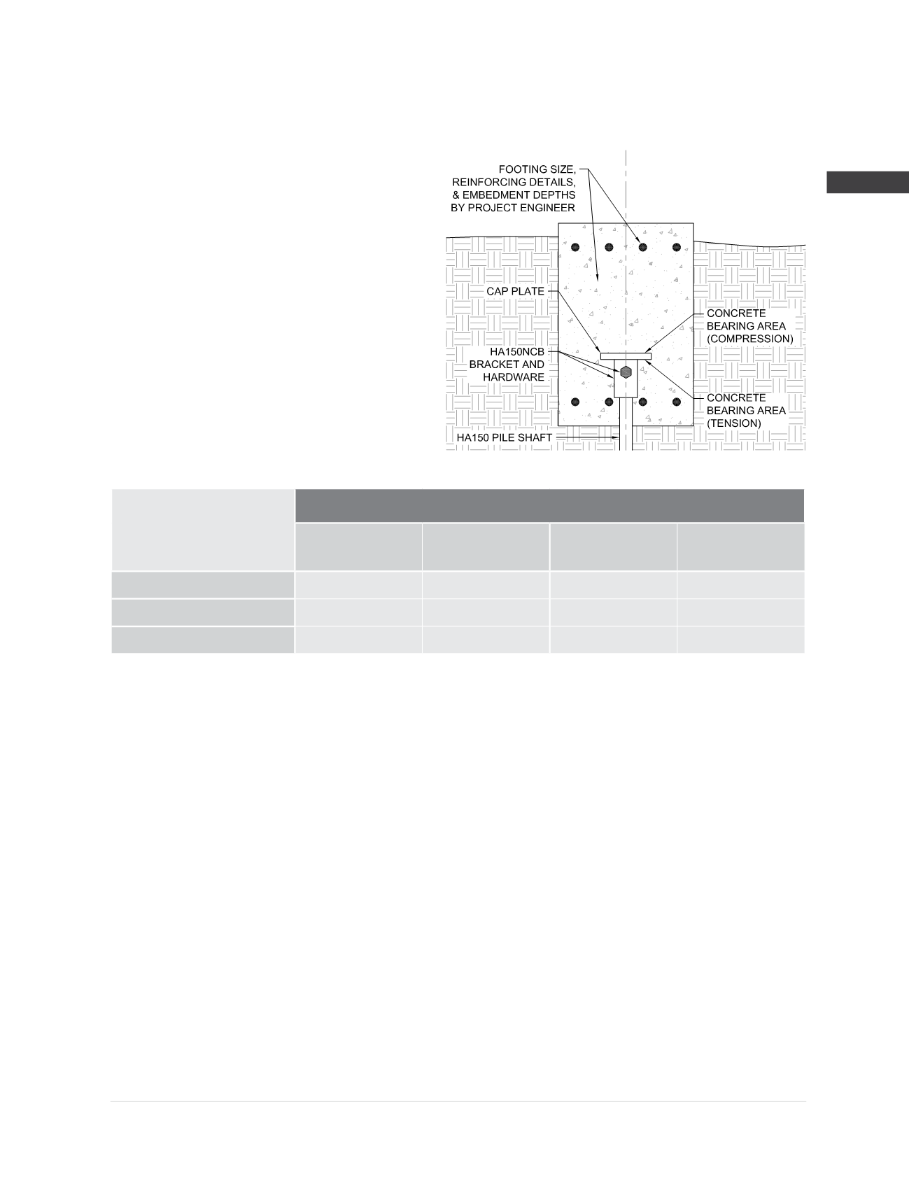
HA150NCB Bracket Specifications and Capacities
when used with the HA150 Helical Pile System
Bracket Sleeve Material:
Ø
2.750” x 0.313” wall
ASTM A513 Type 5 Grade 1026
Yield strength = 70 ksi (min)
Tensile strength = 80 ksi (min)
Cap Plate Material:
3/4
” x 6.00” square
ASTM A36
Bracket Hardware:
(1) -
Ø
3/4
” Grade 8 bolt with nut
Mechanically galvanized per ASTM B695
Bracket Finish:
Available plain or hot-dip galvanized
(2)
Concrete Bearing Area
(5)
(Compression) = 36.0 in
2
Concrete Bearing Area
(5)
(Tension) = 30.1 in
2
Allowable Bracket Capacity
(4)
R
n
/Ω
Compression
(3)
(kips)
Concrete Bearing
(5)
(ksi)
Tension
(kips)
Concrete Bearing
(5)
(ksi)
Plain
29.6
0.82
29.6
0.98
Plain Corroded
(1)
24.9
0.70
24.9
0.84
Galvanized Corroded
(1,2)
27.1
0.76
27.1
0.91
(1)
Corroded capacities include a 50-year scheduled sacrificial loss in thickness per ICC-ES AC358.
(2)
Hot-dip galvanized coating in accordance with ASTM A123.
(3)
Square shaft piles may be considered for compression applications in soil profiles that offer sufficient continuous lateral support; e.g., in
soils with SPT blow counts ≥ 10. In profiles or conditions that limit pile stability, buckling analyses should be considered by the project
engineer, taking into account discontinuities and potential eccentricities created by the couplers.
(4)
Listed capacities include limiting mechanical capacities of the shaft when the shaft and bracket are combined as a system. System
capacity should also not exceed the installed allowable torque-correlated soil capacity (See Shaft Specifications and Capacities).
(5)
Concrete bearing values provided are the uniform bearing stresses required to achieve the full corresponding bracket capacity. Allowable
concrete bearing is a function of several project specific variables including depth of embedment, edge distance, and concrete compressive
strength (f’c). When allowable concrete bearing stresses are lower than these values, corresponding bracket capacities can be obtained
by multiplying the actual allowable concrete bearing stress by the respective bearing areas provided, but should not exceed the capacities
listed in this table. Other concrete design checks including shear, bending, and punching of the supported structure are also project
specific and shall be the responsibility of the project engineer.