


 65 / 365

© 2014 Foundation Supportworks
®
,
Inc.
All Rights Reserved
p 65
APPENDIX 2A
HELICAL PRODUCT RATINGS, PROPERTIES AND DETAILS
Chapter 2
Helical Foundation Systems
Plain
Plain
Corroded
(1)
Galvanized
Corroded
(1,2)
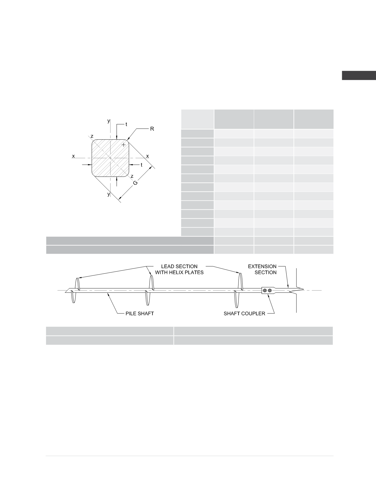
t (in)
1.750
1.714
1.740
G (in)
2.268
2.232
2.258
R (in)
0.250
0.232
0.245
A (in
2
)
3.01
2.89
2.98
I
x
, I
y
(in
4
)
0.75
0.69
0.73
I
z
(in
4
)
0.75
0.69
0.73
S
x
, S
y
(in
3
)
0.85
0.80
0.84
S
z
(in
3
)
0.66
0.62
0.65
Z
x
, Z
y
(in
3
)
1.30
1.22
1.27
Z
z
(in
3
)
1.23
1.16
1.21
r
x
, r
y
(in)
0.50
0.49
0.50
r
z
(in)
0.50
0.49
0.50
Shaft Max Allowable Compression Capacity
(3,4)
P
n
/Ω (kips)
59.6
54.1
54.2
Shaft Max Allowable Tension Capacity
(4)
P
n
/Ω (kips)
59.6
54.1
54.2
HA175 Shaft Specifications and Capacities
Shaft Material:
1.75” round corner square bar
ASTM A29
Yield strength = 90 ksi (min)
Tensile strength = 115 ksi (min)
Helix Plates:
ASTM A572 Grade 50 material
3/8
” thick (standard)
1
” thick (available)
Helix plate geometry conforming to
ICC-ES AC358
Shaft Coupling Hardware:
(2) -
Ø
3/4
” Grade 8 bolts with nuts
Mechanically galvanized per ASTM B695
Surface Finish of Shaft
Segments:
Available plain or hot-dip galvanized
(2)
Default Torque Correlation Factor
(5)
K
t
= 10 (ft
-1
)
Maximum Ultimate Soil Capacity
(6)
Q
u
= 100.0 (kips)
Maximum Installation Torque T = 10,000 (ft-lb)
Maximum Allowable Soil Capacity
(6)
Q
a
= 50.0 (kips) FOS = 2.0
(1)
Corroded properties and capacities include a 50-year scheduled sacrificial loss in thickness per ICC-ES AC358.
(2)
Hot-dip galvanized coating in accordance with ASTM A123.
(3)
Square shaft piles may be considered for compression applications in soil profiles that offer sufficient continuous lateral support; e.g., in soils
with SPT blow counts ≥ 10. In profiles or conditions that limit pile stability, buckling analyses should be considered by the project engineer,
taking into account discontinuities and potential eccentricities created by the couplers.
(4)
Listed mechanical capacities are for the shaft and coupled connections only. System capacity should also not exceed the installed allowable
torque-correlated soil capacity or the allowable capacity of the respective bracket (see additional bracket tables).
(5)
Listed default K
t
factor is consistent with that listed in ICC-ES AC358. This value is generally conservative. Site-specific K
t
factors can be
determined for a given project with full-scale load testing.
(6)
Soil capacities listed are at maximum installation torque. Ultimate soil capacity is based on the equation Q
u
= K
t
x T. Allowable soil capacity
is obtained by dividing the ultimate value by the appropriate factor of safety (Q
a
= Q
u
/ FOS). FOS is most commonly taken as 2.0, although
a higher or lower FOS may be considered at the discretion of the helical pile designer or as dictated by local code or project requirements.
System capacity should also not exceed the mechanical capacity of the shaft or those listed in the respective bracket capacity tables.