


 71 / 365

© 2014 Foundation Supportworks
®
,
Inc.
All Rights Reserved
p 71
APPENDIX 2A
HELICAL PRODUCT RATINGS, PROPERTIES AND DETAILS
Chapter 2
Helical Foundation Systems
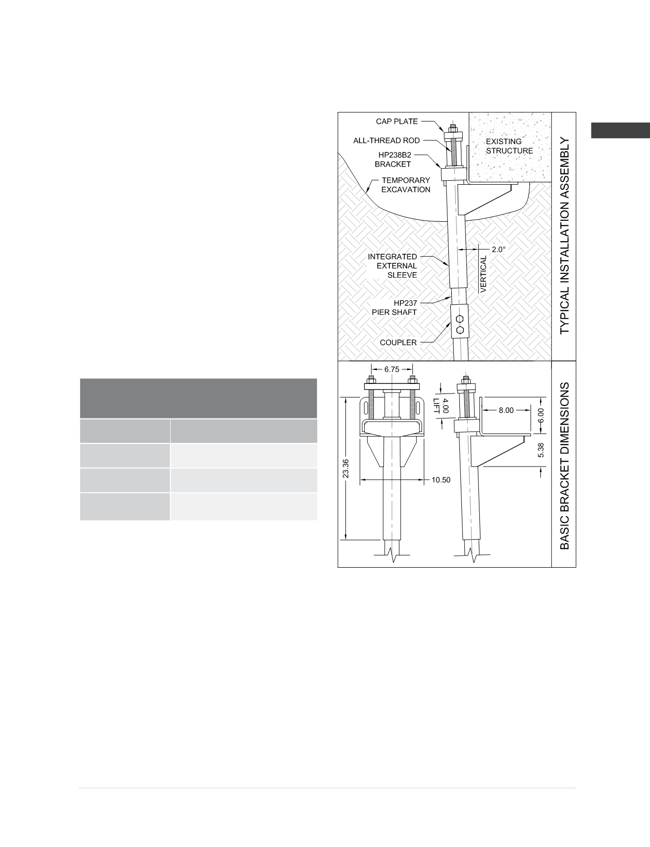
HP238B2 Bracket Specifications and Capacities
when used with the HP237 Helical Pile System
Bracket:
Weldment manufactured from
3/8
”
ASTM A36 plate.
Integrated External Sleeve:
Ø
2.875” x 0.203” wall x 20” long
ASTM A500 Grade B or C
Yield strength = 60 ksi (min)
Tensile strength = 70 ksi (min)
Cap Plate:
1” x 3.00” x 9.00” ASTM A572 Grade 50
with confining ring welded to one side.
Bracket Hardware
(3)
:
(2) -
Ø
3/4
” x 16” long all-thread rod
Grade B7, tensile strength = 125 ksi (min)
Electrozinc plated per ASTM B633
Bracket Finish:
Available plain or hot-dip galvanized
(2)
Allowable Bracket Capacity
(4,5,6,7)
R
n
/Ω
(kips)
Plain
10.9
Plain Corroded
(1)
8.3
Galvanized
Corroded
(1,2)
10.2
(1)
Corroded capacities include a 50-year scheduled sacrificial loss in thickness per ICC-ES AC358.
(2)
Hot-dip galvanized coating in accordance with ASTM A123.
(3)
Optional hardware utilizes similar sized contour (coil) thread made from AISI 1045, tensile strength = 120 ksi. Slightly lower tensile strength
material does not govern the listed capacities.
(4)
Brackets shall be used for support of structures that are considered to be fixed from translation. Structures that are not fixed from
translation shall be braced in some manner prior to installing retrofit brackets systems.
(5)
Allowable capacities consider continuous lateral soil confinement in soils with SPT blow counts ≥ 4. Piles with exposed unbraced lengths or piles
placed in weaker or fluid soils should be evaluated on a case by case basis by the project engineer.
(6)
Concrete bearing assumes a minimum compressive strength (f’c) of 2,500 psi. Local concrete bending and other local design checks should be
evaluated on a case by case basis by the project engineer.
(7)
Listed allowable capacities are for the specific shaft/bracket combination shown. System capacity should also not exceed the installed
torque-correlated soil capacity (See Shaft Specifications and Capacities).