


 114 / 365

© 2014 Foundation Supportworks
®
,
Inc.
All Rights Reserved
p 114
APPENDIX 2B
LIFT ASSEMBLY SPECIFICATIONS
Chapter 2
Helical Foundation Systems
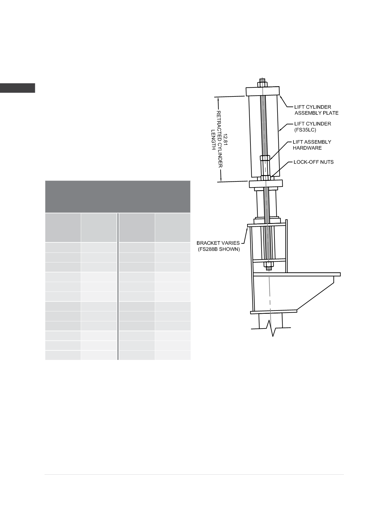
Model 288 Lift Assembly
(2)
Specifications
Compatible Brackets
(4)
:
HP238B2, HP288B2, FS288B
FS288BV, FS288BL, FS288BFM
Lift Cylinder (FS35LC):
Stroke = 4”
Cylinder action = double
Bore =
Ø
3.50”
Hydraulic area = 9.62 in
2
Max operating pressure
(3)
= 8,000 psi
Lift Assembly Hardware
(1,2)
:
(2) -
Ø
3/4
” x 16” long all-thread rod
with nuts and hex couplers, or
(2) -
Ø
3/4
” x 16” long coil rod
with nuts and hex couplers
Lift Assembly
Rated Lifting Load
(3,4)
39.7 kips
Hydraulic
Pressure
(psi)
Lift
Force
(3,4)
(kips)
Hydraulic
Pressure
(psi)
Lift
Force
(3,4)
(kips)
200
1.9
2,600
25.0
400
3.8
2,800
26.9
600
5.8
3,000
28.9
800
7.7
3,200
30.8
1,000
9.6
3,400
32.7
1,200
11.5
3,600
34.6
1,400
13.5
3,700
35.6
1,600
15.4
3,800
36.6
1,800
17.3
3,900
37.5
2,000
19.2
4,000
38.5
2,200
21.2
4,100
39.4
2,400
23.1
4,130
39.7
(1) Hardware used in the lift assembly must be selected to match the hardware used with the installed bracket assembly.
(2)
Note that the only difference between the model 288 and model 350 lift assemblies is the diameter of the threaded rod hardware. All other
components of the two assemblies are identical.
(3)
Do not operate at pressures that produce lift forces in excess of the lift assembly’s rated lifting load. Max operating pressure of the lift
cylinder produces forces that exceed this value and is given for informational purposes only.
(4)
Rated lifting load is given for the lift assembly only. Do not operate at pressures that exceed the allowable capacities of the system which are
governed by the allowable capacities of the bracket and other system components, as well as the torque correlated soil capacity, or installed
driving force divided by an appropriate factor of safety. All of these governing limits are outlined in places elsewhere in this appendix.