


 120 / 365

© 2014 Foundation Supportworks
®
,
Inc.
All Rights Reserved
p 120
APPENDIX 2C
HELIXPRO
®
HELICAL FOUNDATION DESIGN SOFTWARE FOR PROFESSIONALS
Chapter 2
Helical Foundation Systems
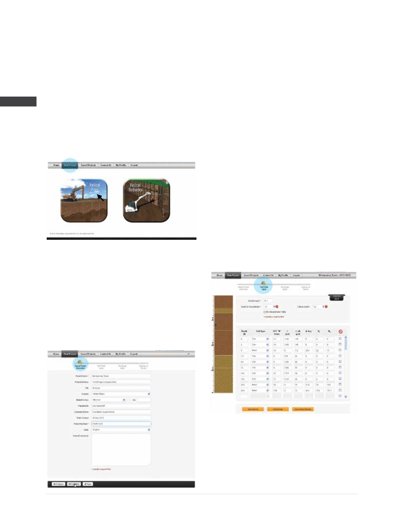
Step 2
The
New Project
page allows the user to choose
between the “Helical Piles” or “Helical Tiebacks”
modules. The helical piles module is selected to
determine capacities of vertical and battered
piles in both tension and compression. The
helical tiebacks module allows the user to create
multiple wall configurations, define the active
zone (failure plane) for each wall and determine
capacities for multiple rows of tiebacks.
The “Helical Piles” button is selected.
Step 3
The
General Project Information
page allows
the user to enter project information and select
either English or Metric units. The project name
and project number are required fields for this
page. The buttons at the bottom allow the user
to save the information on this page, go back
to the previous page or continue to the next
page. Information has been entered for the
Montgomery Tower project located in St. Louis,
MO. Select “Continue” to navigate to the next
screen of data entry.
Step 4
Required fields on the
Soil Profile Inputs
page
include soil boring ID, depth to groundwater,
critical depth and at least one soil layer. Seven
soil types are available including sand, clay,
mixed, organics, sand fill, clay fill and mixed fill.
Soil strength parameter fields for clay, sand, clay
fill and sand fill are populated automatically by
correlation to SPT N-values; however, the user can
manually override these values by entering new
data. Selection of organic or mixed soils requires
manual entry of the soil strength parameters. The
soil profile is graphically displayed as the data
is entered. Multiple borings can be entered and
saved. The help menu is accessed by clicking
on the question mark icons next to various entry
fields. In this example, the user has entered and
saved the information from Boring B-1 and is
ready to continue to the next page.
Step 5
The
Pile Design Inputs
page requires input for
boring ID, pile ID, pile shaft type, helix plate
configuration and geometry, pile length, batter
angle and pile head depth. After required fields