


 119 / 365

© 2014 Foundation Supportworks
®
,
Inc.
All Rights Reserved
p 119
APPENDIX 2C
HELIXPRO
®
HELICAL FOUNDATION DESIGN SOFTWARE FOR PROFESSIONALS
Chapter 2
Helical Foundation Systems
HELIXPRO
®
HELICAL FOUNDATION DESIGN
SOFTWARE FOR PROFESSIONALS
HelixPro is a state-of-the-art web-based program
that allows the user to calculate bearing and uplift
capacitiesofhelicalpilesaswellastensioncapacities
of helical tiebacks as they pertain to project specific
site conditions and soil profiles. The program is
ideal for analyzing both vertical and battered piles
for deep foundations of new structures, seismic
retrofitting applications, tension/uplift elements
of guyed structures, tiebacks for earth retention
systems, tiedowns, and more. HelixPro calculates
capacities of helical piles and tiebacks using the
Individual Bearing Method, which is referenced in
Chapter 2 of the FSI Technical Manual.
HelixPro allows the user to quickly perform
multiple trials with varying soil profiles and helix
configurations to select the most economical and
practical solution for the project. The program
provides a step-by-step “wizard” approach through
the design process, making the program intuitive
and easy to navigate. Some of the many features of
the software include:
• Video tutorials available on the FSI website:
www.OnStableGround.com• Help menus and buttons along the way to further
assist the user through the design process
• Pop-up warnings to alert the user when the
torsional rating of the shaft is exceeded, when
non-standard helix plate configurations are
selected, when minimum depth or embedment
criteria are violated, etc.
• Graphical representation of soil layers and
helix plate depths
• Graphical representation of installation torque
with depth, along with boundary lines to
represent the torsional rating of the shaft
• Generation of a summary report with a graphical
representation of the proposed installation
• Ability to save and manage projects and sort these
projects by date, application and project status
• Links to case studies, current and previous
issues of the Foundation Nation for Design
Professionals (FNDP) newsletter, and technical
content on the FSI website
The software’s layout and functionality are
illustrated in the following guide and design
example. The example utilizes real soil and project
information for a guyed tower project completed
in St. Louis, Missouri. The tower supports were
retrofitted with helical piles and anchors to provide
additional support and stability. The example is for
the design of the southwest guy support where
two Model 150 square shaft helical anchors were
installed at a 40 degree batter.
Software Guide and Design Example
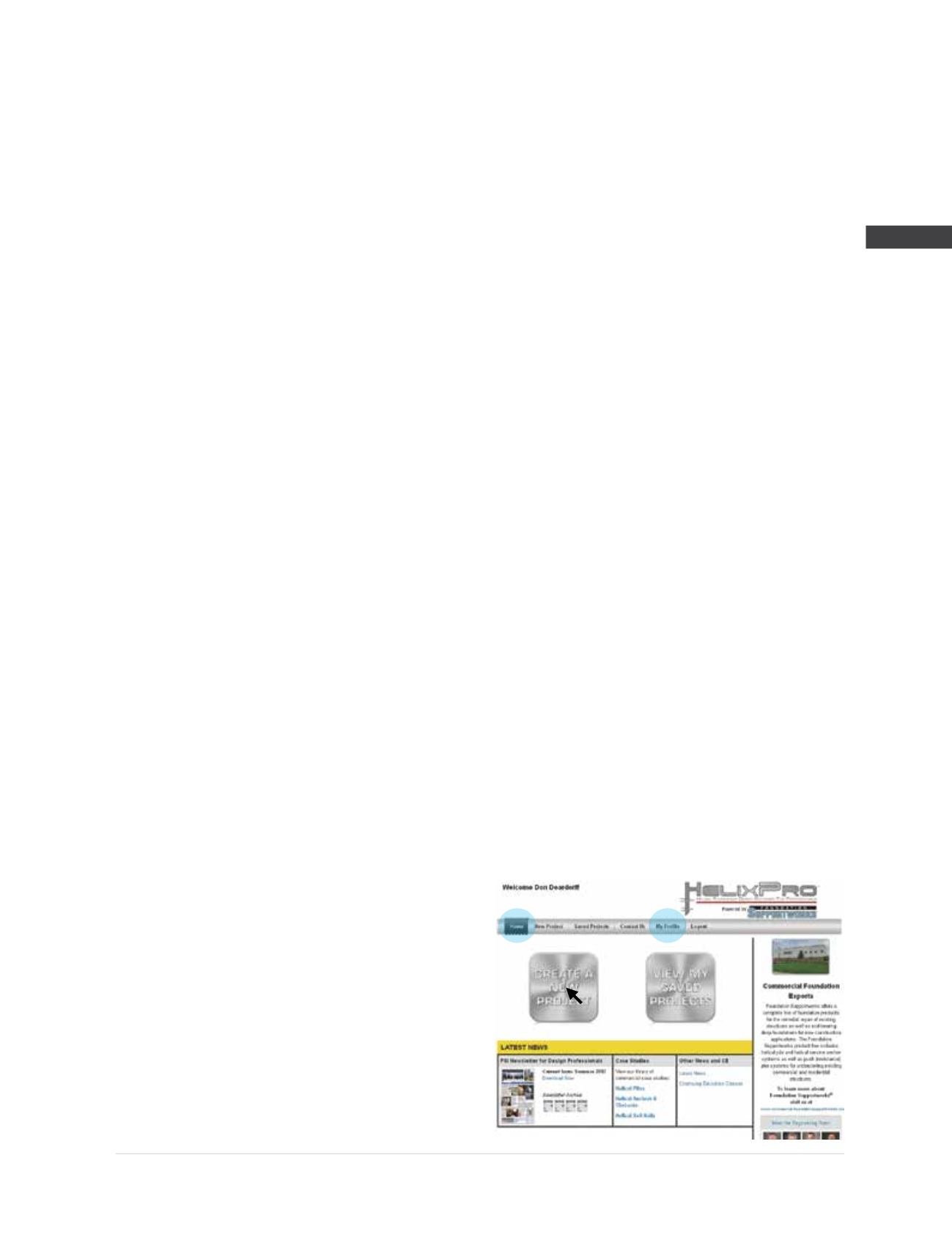
Step 1
Following log-in, the program opens to the
Home
page where the user can create a new project or
view saved projects. The top menu bar also allows
access to
My Profile
where user information
is input. User name and company name are
automatically incorporated into the final report.
The
Home
page also has links to FSI case studies,
newsletters and other technical information.
For this example the “Create A New Project” button
is selected.