


 267 / 365

© 2014 Foundation Supportworks
®
,
Inc.
All Rights Reserved
p 267
APPENDIX 3B
DRIVE STAND SPECIFICATIONS
Chapter 3
Hydraulically-Driven Push Piers
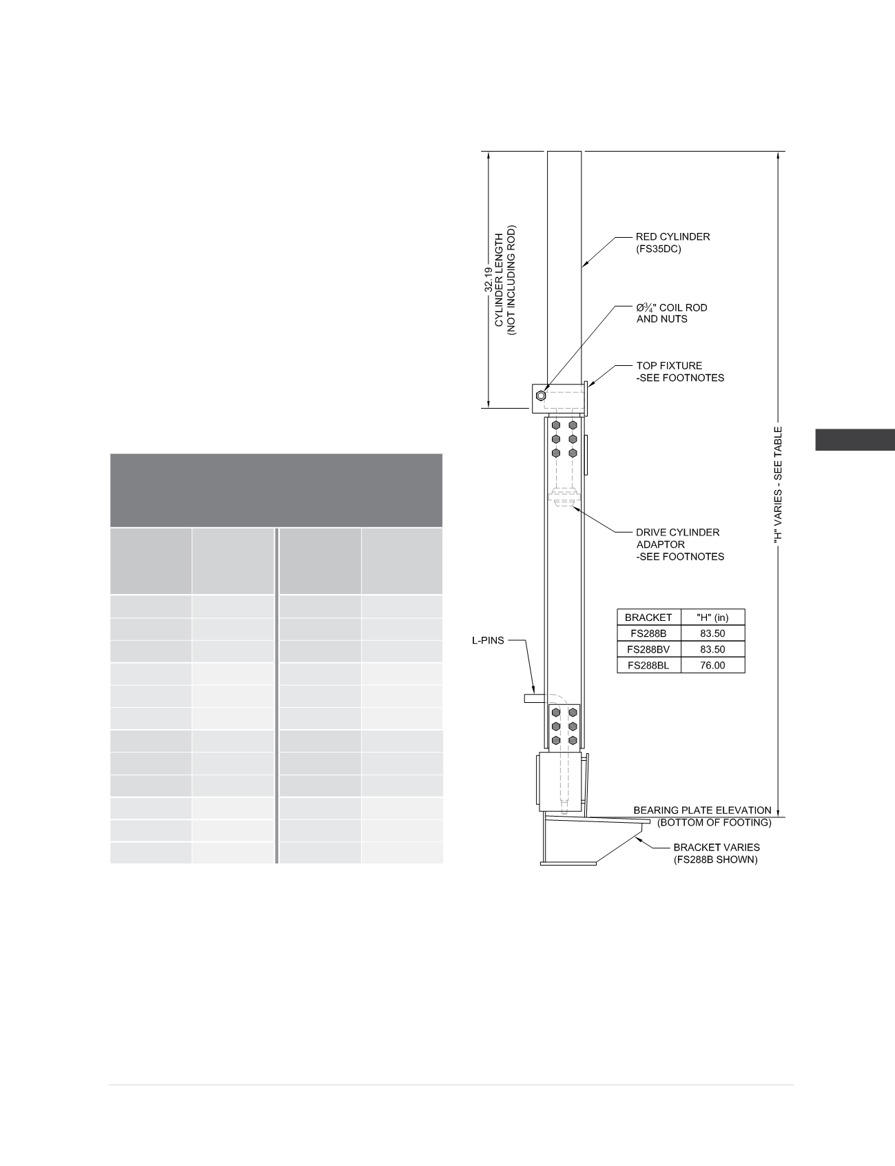
Model 288 Drive Stand Specifications
when used with the RED
(5)
Drive Cylinder (FS35DC)
Compatible Brackets
(3)
:
FS288B, FS288BV,
FS288BL, FS288BFM
Drive Cylinder
(5)
(FS35DC):
Stroke = 22”
Cylinder action = double
Bore =
Ø
3.50”
Hydraulic area = 9.62 in
2
Max operating pressure
(2)
= 8,000 psi
Drive Cylinder Adaptor
(4)
:
FSDCA (reversible)
Drive Stand Hardware
(1)
:
(1) -
Ø
3/4
” x 12” long coil rod with nuts
(2) -
Ø
1” x 15” long L-pins
Drive Stand Rated Drive Load
(2,3)
60.0 kips
Hydraulic
Pressure
(psi)
Drive
Force
(2,3)
(kips)
Hydraulic
Pressure
(psi)
Drive
Force
(2,3)
(kips)
400
3.8
4,200
40.4
800
7.7
4,400
42.3
1,200
11.5
4,600
44.3
1,600
15.4
4,800
46.2
2,000
19.2
5,000
48.1
2,400
23.1
5,200
50.0
2,800
26.9
5,400
52.0
3,200
30.8
5,600
53.9
3,400
32.7
5,800
55.8
3,600
34.6
6,000
57.7
3,800
36.6
6,200
59.7
4,000
38.5
6,235
60.0
(1)
Drive stand should never be operated without all hardware components firmly in place.
(2)
Do not operate at pressures that produce drive forces in excess of the drive stand’s rated drive load. Max operating pressure of the drive
cylinder produces forces that exceed this value and is given for informational purposes only.
(3)
Do not operate at pressures that produce drive forces in excess of the “maximum drive force during installation” values specified for the
bracket being installed (see Bracket Specifications and Capacities).
(4)
Drive cylinder adaptor FSDCA is a reversible adaptor that is compatible with both PP288 and PP350 push pier systems. Assemble the
adaptor to the cylinder rod in the appropriate orientation for the corresponding pier size being installed.
(5)
Note that the mounting flange dimensions are different between the RED and GRAY cylinders (FS35DC and FS425DC) and thereby require
the use of unique top fixture weldments that correspond to the appropriate drive cylinder.