


 270 / 365

© 2014 Foundation Supportworks
®
,
Inc.
All Rights Reserved
p 270
APPENDIX 3B
DRIVE STAND SPECIFICATIONS
Chapter 3
Hydraulically-Driven Push Piers
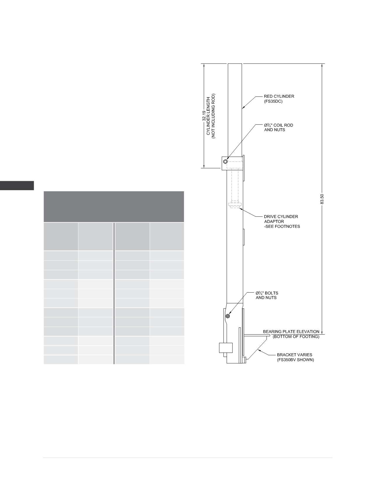
Model 350 Drive Stand Specifications
when used with the RED Drive Cylinder (FS35DC)
Compatible Brackets
(2,3)
:
FS350BV, FS400BV
Drive Cylinder (FS35DC):
Stroke = 22”
Cylinder action = double
Bore =
Ø
3.50”
Hydraulic area = 9.62 in
2
Max operating pressure = 8,000 psi
Drive Cylinder Adaptors
(3)
:
FSDCA (reversible) with FS350BV
FSDCA400 with FS400BV
Drive Stand Hardware
(1)
:
(1) -
Ø
3/4
” x 12” long coil rod with nuts
(2) -
Ø
3/4
” grade 8 bolts with nuts
Drive Stand Rated Drive Load
(2)
77.0 kips
Hydraulic
Pressure
(psi)
Drive
Force
(2)
(kips)
Hydraulic
Pressure
(psi)
Drive
Force
(2)
(kips)
400
3.8
5,200
50.0
800
7.7
5,600
53.9
1,200
11.5
6,000
57.7
1,600
15.4
6,400
61.6
2,000
19.2
6,600
63.5
2,400
23.1
6,800
65.4
2,800
26.9
7,000
67.3
3,200
30.8
7,200
69.3
3,600
34.6
7,400
71.2
4,000
38.5
7,600
73.1
4,400
42.3
7,800
75.0
4,800
46.2
8,000
77.0
(1)
Drive stand should never be operated without all hardware components firmly in place.
(2)
Do not operate at pressures that produce drive forces in excess of the “maximum drive force during installation” values specified for the
bracket being installed (see Bracket Specifications and Capacities).
(3)
PP350 and PP400 push pier systems require the use of different drive cylinder adaptors. Assemble the appropriate adaptor to the cylinder
rod for the corresponding pier size being installed. Also note that drive cylinder adaptor FSDCA is reversible and needs to be assembled in
the appropriate orientation when installing PP350 systems.