


 275 / 365

© 2014 Foundation Supportworks
®
,
Inc.
All Rights Reserved
p 275
APPENDIX 3C
LIFT ASSEMBLY SPECIFICATIONS
Chapter 3
Hydraulically-Driven Push Piers
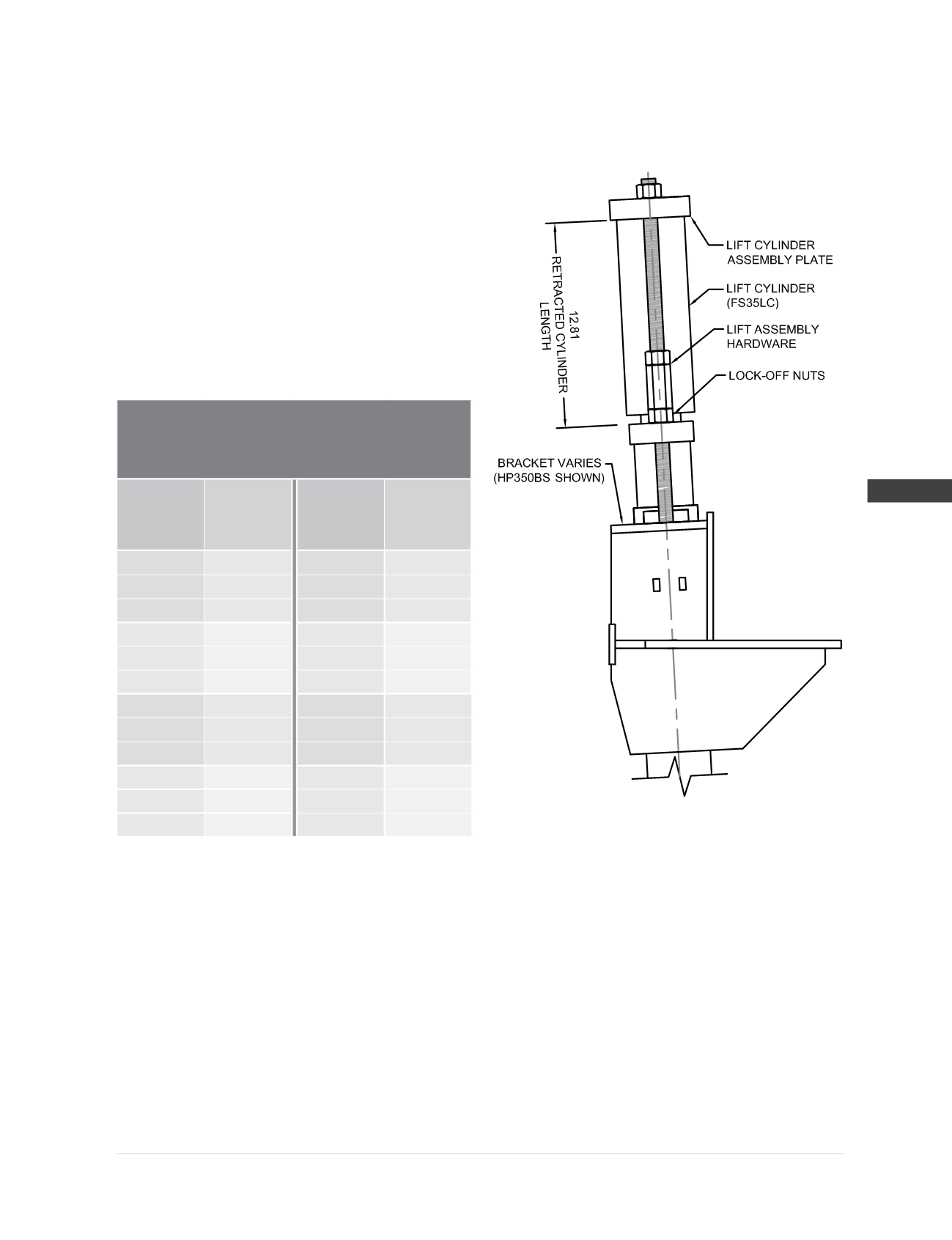
Model 350 Lift Assembly
(1)
Specifications
Compatible Brackets
(3)
:
HP350BS, HP350B,
FS350BV, FS400BV
Lift Cylinder (FS35LC):
Stroke = 4”
Cylinder action = double
Bore =
Ø
3.50”
Hydraulic area = 9.62 in
2
Max operating pressure
(2)
= 8,000 psi
Lift Assembly Hardware
(1)
:
(2) -
Ø
7/8
” x 18” long all-thread rod
with nuts and hex couplers
Lift Assembly
Rated Lifting Load
(2,3)
56.3 kips
Hydraulic
Pressure
(psi)
Lift
Force
(2,3)
(kips)
Hydraulic
Pressure
(psi)
Lift
Force
(2,3)
(kips)
400
3.8
3,800
36.6
800
7.7
4,000
38.5
1,200
11.5
4,200
40.4
1,600
15.4
4,400
42.3
2,000
19.2
4,600
44.3
2,400
23.1
4,800
46.2
2,600
25.0
5,000
48.1
2,800
26.9
5,200
50.0
3,000
28.9
5,400
52.0
3,200
30.8
5,600
53.9
3,400
32.7
5,800
55.8
3,600
34.6
5,850
56.3
(1)
Note that the only difference between the model 288 and model 350 lift assemblies is the diameter of the threaded rod hardware. All other
components of the two assemblies are identical.
(2)
Do not operate at pressures that produce lift forces in excess of the lift assembly’s rated lifting load. Max operating pressure of the lift cylinder
produces forces that exceed this value and is given for informational purposes only.
(3)
Rated lifting load is given for the lift assembly only. Do not operate at pressures that exceed the allowable capacities of the system which are
governed by the allowable capacities of the bracket and other system components, as well as the torque correlated soil capacity, or installed
driving force divided by an appropriate factor of safety. All of these governing limits are outlined in places elsewhere in this appendix.