


 313 / 365

© 2014 Foundation Supportworks
®
,
Inc.
All Rights Reserved
p 313
APPENDIX 4A
GEO-LOCK® WALL ANCHOR SYSTEM
Chapter 4
Miscellaneous Structural Support Products
Geo-Lock
®
WALL ANCHOR SYSTEM
Technical Specifications
Plate Steel:
ASTM A1011 C1008-C1010, 10 gauge plate
embossed with two (2) longitudinal ribs.
Wall Plates:
Two sizes: 12” x 18” and 12” x 28”
Earth Plates:
Fabricated from two wall plates
welded in a cross pattern. One inch
on each end of wall plates are bent
90 degrees. Three sizes: 16” x 16”,
16” x 26”, and 26” x 26”.
All-Thread Rod:
Medium Carbon Steel. Tensile strength = 85
ksi (min.), - 10 UNC 2A, 80” long
(assembly consists of two rods). Allowable
tensile capacity = 14 kips.
Rod Coupler:
AISI 1144 Yield strength = 100 ksi
(min.), Tensile strength = 115 ksi (min.)
- 10 UNC 2B, oversized tap, 3” long x
0.984” diameter.
Termination Hardware:
SAE J995 Grade 2 heavy square nuts
- 10 UNC 2B, oversized tap.
Finish:
All components are hot-dip galvanized in
accordance with ASTM A123 or ASTM A153.
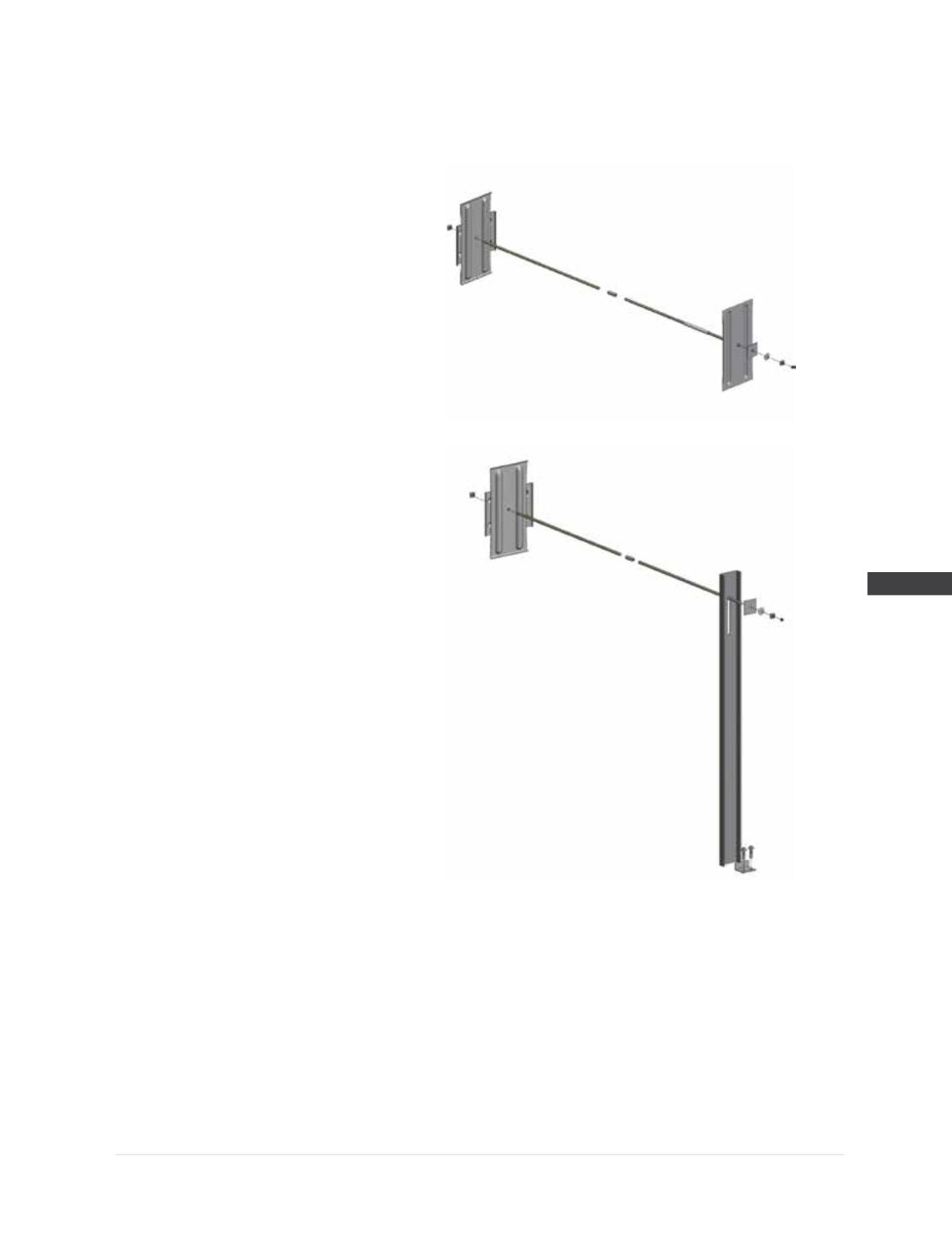
Alternate Wall Bracing Detail:
C6 x 8.2 steel channel, ASTM A36.
Channel secured at base with steel bracket
or cast into concrete. Bracket is 3.75” x
1.75” x 0.25” thick x 4.5” long bent plate,
ASTM A36, with (2)
Ø
0.875 holes.
(2)
Ø
0.75” x 2.5” sleeve anchors.
1.
Installation of any tieback or anchor system in potential landslide or hillside creep soils should be designed by a professional engineer.
2.
Refer to Section 4.2.4 of the FSI Technical Manual for recommendations on anchor spacing, depth and location of earth plate, and installation
torque.
Standard Wall Plate Detail
Alternate Channel Detail