


 338 / 365

© 2014 Foundation Supportworks
®
,
Inc.
All Rights Reserved
p 338
Chapter 5
PolyLEVEL
®
Polyurethane Foam and Resin
CHAPTER 5
POLYLEVEL
®
POLYURETHANE FOAM AND RESIN
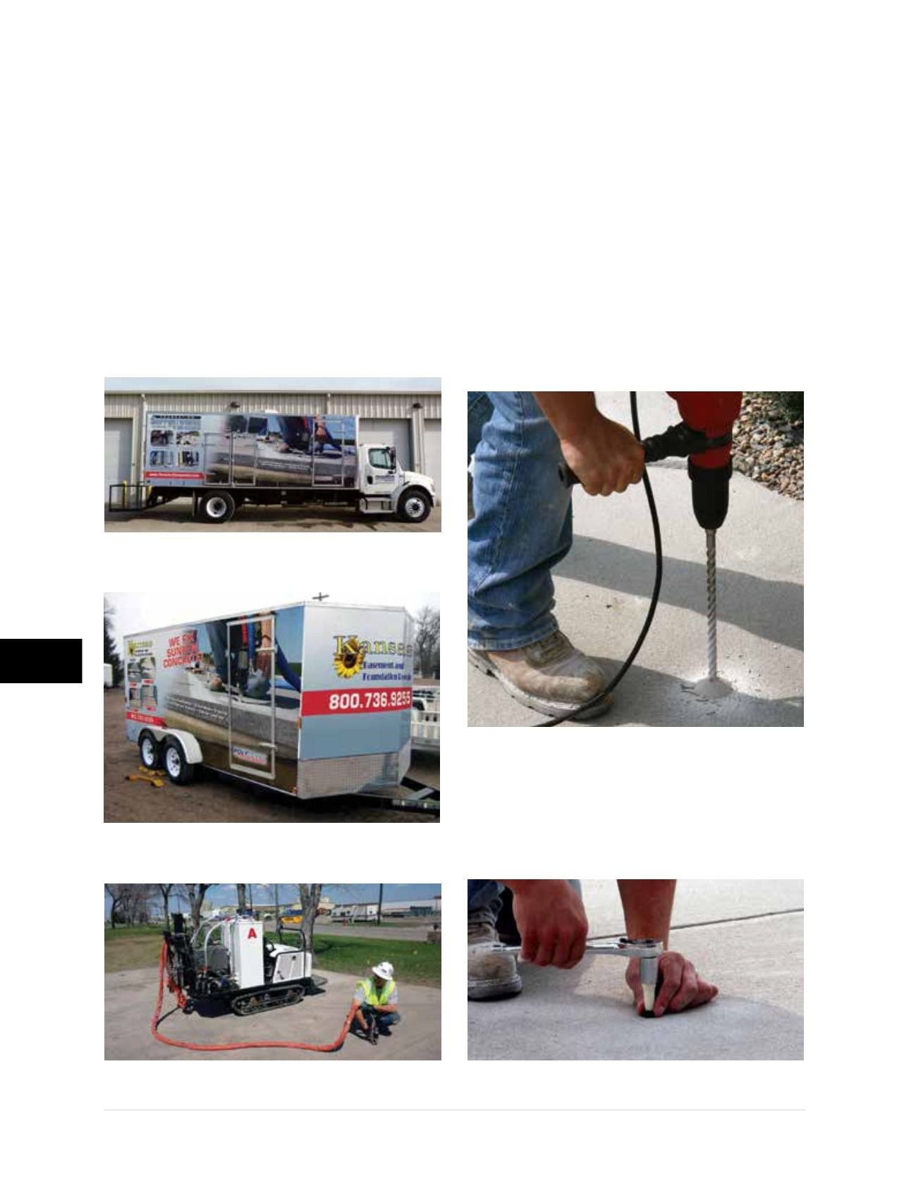
5.6 Equipment
PolyLEVEL is installed with custom-built
installation rigs available as truck-mounted
(Figure 5.6.a1)
, trailer units
(Figure 5.6.a2)
, or ATV
buggies
(Figure 5.6.a3)
. The basic components
of the system include material storage tanks, a
generator, an air compressor, pumps, a reactor,
and applicator(s)/gun(s). The reactor includes
a proportioner, heater, and insulated and
heated hoses. This ensures that the two parts
are delivered to the applicator at a consistent
pressure and temperature.
5.7 Installation Steps
The following installation steps provide a broad
overview of PL 250, PL 400 and PL 400H
injection beneath a concrete slab or pavement.
Intermediate steps, installation equipment and
tools used, and considerations for unusual
conditions or applications are not addressed.
Step 1
–
5/8
-inch holes are drilled in strategic
locations in the slab
(Figure 5.7.a1)
. In general,
the holes are spaced 5 feet apart and 3 feet from
edges of the slab. Locations and spacing are often
modified in the field to achieve the desired result.
Step 2
– Injection ports are placed and
tightened with a socket and wrench to seal the
hole
(Figure 5.7.a2)
.
Figure 5.6.a1
Truck-mounted installation equipment
Figure 5.6.a2
Enclosed trailer unit
Figure 5.6.a3
ATV buggy
Figure 5.7.a1
Figure 5.7.a2