


 101 / 365

© 2014 Foundation Supportworks
®
,
Inc.
All Rights Reserved
p 101
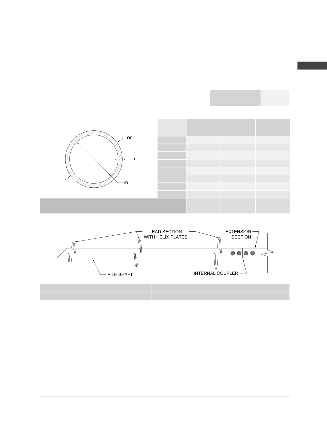
APPENDIX 2A
HELICAL PRODUCT RATINGS, PROPERTIES AND DETAILS
Chapter 2
Helical Foundation Systems
Plain
Plain
Corroded
(1)
Galvanized
Corroded
(1,2)
OD (in)
4.500
4.464
4.490
t (in)
0.313
0.277
0.303
ID (in)
3.874
3.910
3.884
A (in
2
)
4.12
3.64
3.99
I (in
4
)
9.07
8.02
8.78
S (in
3
)
4.03
3.59
3.91
Z (in
3
)
5.50
4.86
5.32
r (in)
1.48
1.48
1.48
Shaft Max Allowable Compression Capacity
(4,5)
P
n
/Ω (kips)
123.3
109.1
119.3
Shaft Max Allowable Tension Capacity
(5)
P
n
/Ω (kips)
59.1
50.8
56.7
HP450 Shaft Specifications and Capacities
Shaft Material:
Ø
4.500” x 0.337” wall
ASTM A500 Grade B or C
Yield strength = 50 ksi (min)
Tensile strength = 60 ksi (min)
Shaft Coupler Material:
Ø
3.750” x 0.500” wall
ASTM A513 Type 5 Grade 1026
Yield strength = 70 ksi (min)
Tensile strength = 80 ksi (min)
Helix Plates:
ASTM A572 Grade 50 material
3/8
” thick (standard)
1
” thick (available)
Helix plate geometry conforming to
ICC-ES AC358
Shaft Coupling Hardware:
(4) -
Ø
1-
1/8
” Grade 5 bolts with nuts
Electrozinc plated per ASTM B633
Surface Finish of Shaft
Segments:
Available plain or hot-dip galvanized
(2)
Nominal Thickness
0.337 (in)
Design Thickness
(3)
0.313 (in)
Torque Correlation Factor
(6)
K
t
= 6 (ft
-1
)
Maximum Ultimate Soil Capacity
(7)
Q
u
= 132.0 (kips)
Maximum Installation Torque T = 22,000 (ft-lb)
Maximum Allowable Soil Capacity
(7)
Q
a
= 66.0 (kips) FOS = 2.0
(1)
Corroded properties and capacities include a 50-year scheduled sacrificial loss in thickness per ICC-ES AC358.
(2)
Hot-dip galvanized coating in accordance with ASTM A123.
(3)
Design thickness for HSS and Pipe based on 93% of nominal thickness per AISC.
(4)
Allowable mechanical compression capacities consider continuous lateral soil confinement in soils with SPT blow counts ≥ 4. Piles with
exposed unbraced lengths or piles placed in weaker or fluid soils should be evaluated on a case by case basis by the project engineer.
(5)
Listed mechanical capacities are for the shaft and coupled connections only. System capacity should also not exceed the installed allowable
torque-correlated soil capacity or the allowable capacity of the respective bracket (see additional bracket tables).
(6)
Listed K
t
factor is that recommended by FSI. Site-specific K
t
factors can be determined for a given project with full-scale load testing.
(7)
Soil capacities listed are at maximum installation torque. Ultimate soil capacity is based on the equation Q
u
= K
t
x T. Allowable soil capacity
is obtained by dividing the ultimate value by the appropriate factor of safety (Q
a
= Q
u
/ FOS). FOS is most commonly taken as 2.0, although
a higher or lower FOS may be considered at the discretion of the helical pile designer or as dictated by local code or project requirements.
System capacity should also not exceed the mechanical capacity of the shaft or those listed in the respective bracket capacity tables.