


 127 / 365

© 2014 Foundation Supportworks
®
,
Inc.
All Rights Reserved
p 127
APPENDIX 2D
PILE BUCKING CONSIDERATIONS
Chapter 2
Helical Foundation Systems
Example
Consider a fully embedded pile installed to a
depth of 25 feet within a soil profile consisting
of 15 feet of very soft clay with an average SPT
N-value = 1 bpf and an average cohesion value
= 200 psf. The very soft clay layer is underlain
by a dense sand which extends beyond the pile
tip. Based on the pile design, a pinned-pinned
boundary condition is selected. A HP287 pile is
considered with the following parameters:
E
p
= 29(10
6
) psi
I
p
= 1.445 in
4
for plain steel (plain corroded
or galvanized corroded could also be
considered)
d
= 2.875 in. for plain steel (plain corroded
or galvanized corroded could also be
considered)
L
= 15 ft. = 180 in.
Based on the cohesion of 200 psf, a design
value of k
h
= 20 pci is selected from
Figure 2D.2
.
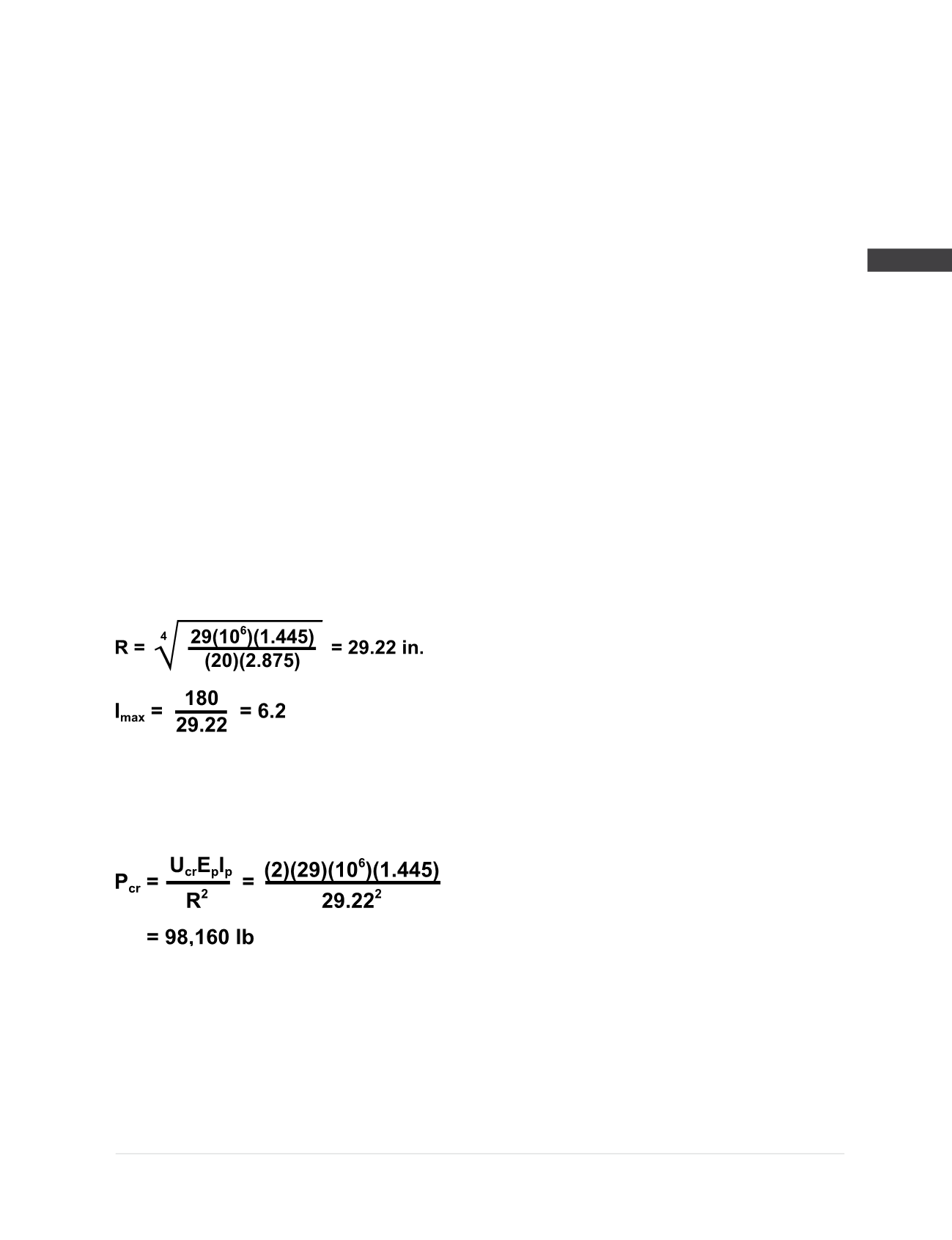
From
Figure 2D.1
, with I
max
= 6.2 and assuming
pinned-pinned (p-p) boundary conditions, U
cr
=
2.0. The critical buckling load (P
cr
) can then be
calculated from the design equation:
Divide the critical buckling load by an appropriate
FOS to determine the allowable pile capacity to
prevent buckling.