


 125 / 365

© 2014 Foundation Supportworks
®
,
Inc.
All Rights Reserved
p 125
APPENDIX 2D
PILE BUCKING CONSIDERATIONS
Chapter 2
Helical Foundation Systems
PILE BUCKLING CONSIDERATIONS
Buckling of helical piles is generally only
considered when soil conditions consist of very
soft clays or very loose sands with SPT N-values
less than 4 blows per foot (bpf). Research has
shown that soils with SPT N-values greater than
or equal to 4 bpf provide sufficient lateral support
to prevent buckling, however, determination
of pile buckling is a complex problem that is
affected by coupling strength/stiffness, pile
batter, shaft section and elastic properties, load
type and eccentricity, length of exposed pile
shaft and soil strength.
The methods described in this section for
buckling evaluation may not account for dynamic
loading, partial embedment (exposed pile), pile
geometry changes, and stiffness variations
due to pile shaft couplings. The methods may
be applicable for cases where fully-embedded
grout filled pipe piles (with couplings) are used,
or for fully-embedded piles without couplings.
The design professional should be aware of the
buckling design method assumptions as they
apply to the helical pile design.
After the critical buckling load is calculated, a
factor of safety (FOS) is applied to determine the
allowable pile capacity to prevent buckling. A FOS
of 1.67 would be consistent with AISC design
methods, although helical pile designers routinely
use factors of safety in the range of 1.5 to 2.0.
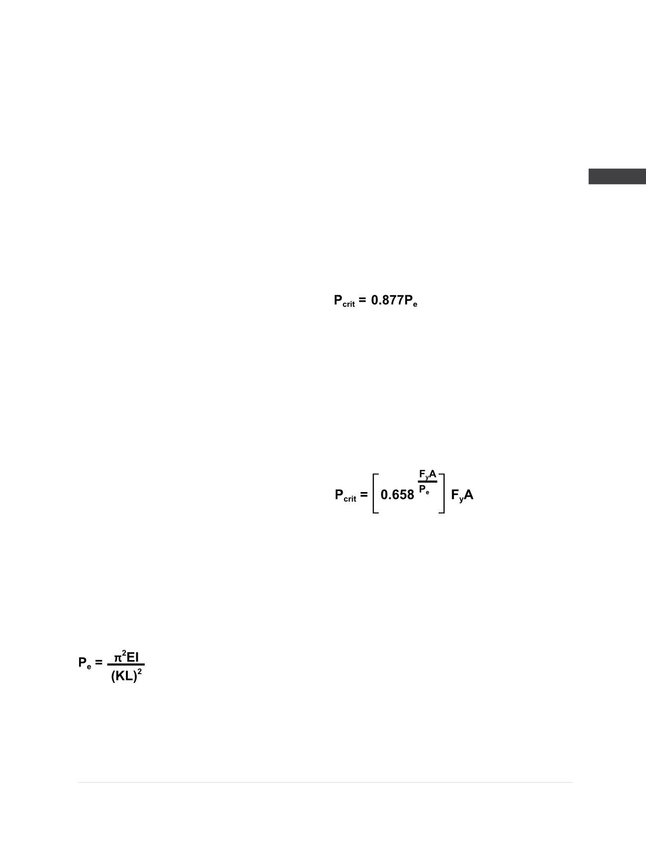
Euler Method
The Euler equation shown below provides an
estimation of the elastic critical buckling load for
a long, slender, ideal column:
Where,
P
e
= Elastic Critical Buckling Load
E
= Modulus of Elasticity of the Pile Shaft
Cross Section
I
= Moment of Inertia of the Pile Shaft
Cross Section
K
= Effective Length Factor
L
= Unsupported Length
An ideal column is one that is perfectly straight,
homogeneous, and free from any initial residual
stresses. Since an ideal column can only exist in
theory, AISC utilizes an adjustment coefficient to
normalize the theoretical elastic buckling with
the results observed in testing research. The
elastic critical buckling load then becomes:
Where,
P
crit
= Critical Buckling Load
It should be noted that the Euler Method is only
suitable for intermediate length to longer
columns that produce values of P
e
less than
0.44F
y
A. When the Euler load (P
e
) is greater than
this value, then inelastic buckling will govern
and P
crit
becomes:
Where,
F
y
= Yield Stress
A
= Cross Sectional Area
These equations for elastic and inelastic
buckling would be applicable to helical piles
installed without lateral soil support; e. g., piles
with exposed lengths above the ground surface
or piles penetrating fluid soils (SPT N-values =
0). In most other conditions, the critical buckling
load determined using these equations may be
overly conservative.