


 210 / 365

© 2014 Foundation Supportworks
®
,
Inc.
All Rights Reserved
p 210
APPENDIX 2H
DOCUMENTATION
Chapter 2
Helical Foundation Systems
ESR-3074
|
Most Widely Accepted and Trusted
Page 6 of 9
5.14
The minimum helical pile center-to-center spacing
must be three times the largest helical bearing plate
diameters. For piles with closer spacing, the pile
allowable load reductions due to pile group effects
must be included in the geotechnical report
described in Section 4.1.1 of this report, and must be
considered in the pile design by a registered design
professional. The spacing and load reductions, if
applicable, are subject to the approval of the code
official.
5.15
For piles supporting tension loads, the piles must be
installed such that the minimum depth from the
ground surface to the uppermost helix is 12D, where
D is the diameter of the largest helix. In cases where
the installation depth is less than 12D, the minimum
embedment depth must be determined by a
registered design professional based on site-specific
soil conditions, and the determination is subject to
the approval of the code official. For tension
applications where the helical pile is installed at an
embedment depth of less than 12D, the torque-
correlation soil capacity, P4, is outside of the scope
of this evaluation report.
5.16
Piles supporting compression loads must be
installed such that the minimum depth from the
bottom of the pile-supported footing to the
uppermost helix is no less than 5 feet (1524 mm).
For compression piles with a shallower helix depth,
the actual helix depth must be considered in the pile
design by a registered design professional. The
depth is subject to approval of the code official.
5.17
Evaluation of compliance with Section 1810.3.11.1 of
the 2012 and 2009 IBC (Section 1808.2.23.1.1 of the
2006 IBC) for buildings assigned to Seismic Design
Category (SDC) C, and with Section 1810.3.6 of the
2012 and 2009 IBC (Section 1808.2.7 of the 2006
IBC) for all buildings, is outside the scope of this
evaluation report. Such compliance must be
addressed by a registered design professional for
each site, and the work of the design professional is
subject to approval of the code official.
5.18
Requirements listed in the footnotes to Tables 1, 2,
3, and 5 must be satisfied.
5.19
Settlement of helical piles is beyond the scope of this
evaluation report, and must be determined by a
registered design professional as required in Section
1810.2.3 of the 2012 and 2009 IBC (Section
1808.2.12 of the 2006 IBC).
5.20
The FSI helical foundation systems are
manufactured at the following facilities: Distefano
Technology & Manufacturing Company, 3838 South
108
th
Street,
Omaha,
Nebraska;
Behlen
Manufacturing Company, 4025 East 23
rd
Street,
Columbus, Nebraska; and TSA Manufacturing,
14901 Chandler Road, Omaha, Nebraska.
Manufacturing is done under a quality control
program with inspections by ICC-ES.
6.0 EVIDENCE SUBMITTED
Data in accordance with the ICC-ES Acceptance Criteria
for Helical Pile Systems and Devices (AC358), dated
June 2013.
7.0 IDENTIFICATION
The FSI helical foundation system components described
in this report are identified by labels that include the report
holder’s name (Foundation Supportworks, Inc.); the name
and address of Distefano Technology & Manufacturing
Company, Behlen Manufacturing Company, or TSA
Manufacturing; the product name; the model number
(HP288); the part number; the evaluation report number
(ESR-3074).
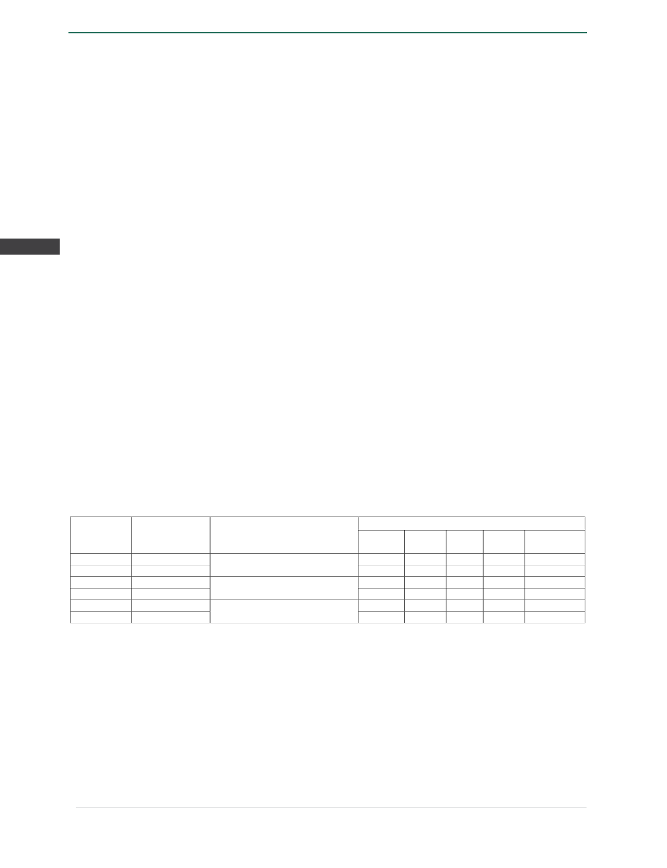
TABLE 1—HP288 (WITH RETROFIT BRACKETS) ASD COMPRESSION CAPACITIES
Bracket Part
No.
1
Sleeve Part No.
1
HP288 Bracket Description
Allowable Compression Capacity (kips)
Bracket
(P1)
2
Shaft
(P2)
3
Helix
(P3)
4
Soil
(P4)
5
Foundation
System
6
FS288B
FS288ES30
Standard Bracket w/30" Sleeve
24.9
60
55
35.5
24.9
FS288B-G
FS288ES30-G
27.9
60
55
35.5
27.9
FS288B
FS288ES48
Standard Bracket w/48" Sleeve
31.4
60
55
35.5
31.4
FS288B-G
FS288ES48-G
35.1
60
55
35.5
35.1
FS288BL
FS288ES30
Low Profile Bracket w/30" Sleeve
25.3
60
55
35.5
25.3
FS288BL-G
FS288ES30-G
28.2
60
55
35.5
28.2
For
SI:
I inch = 25.4 mm, 1 kip = 1000 lbf = 4.448 kN.
1
Part numbers with “G” suffix indicate hot-dip galvanized coating. Part numbers without a “G” suffix indicate plain steel.
2
Bracket capacity is based on full scale load tests per AC358 with an installed 5'-0" unbraced pile length per Section 1810.2.1 of the 2012 and
2009 IBC (Section 1808.2.9.2 of the 2006 IBC), having a maximum of one coupling.
3
Shaft capacity is applicable only to the foundation systems that are fully braced as described in Section 4.1.3.
4
Helix capacity is based on a single helix plate with outer diameter of 8, 10, 12 or 14 inches (203, 254, 305 or 356 mm).
5
Soil capacity is based on torque correlation per Section 4.1.5 of this report, with piles installed at the maximum torsion rating.
6
Foundation system allowable capacity is based on the lowest of P1, P2, P3 and P4 listed in this table. See Section 4.1.6 for additional
requirements.