


 211 / 365

© 2014 Foundation Supportworks
®
,
Inc.
All Rights Reserved
p 211
APPENDIX 2H
DOCUMENTATION
Chapter 2
Helical Foundation Systems
ESR-3074
|
Most Widely Accepted and Trusted
Page 7 of 9
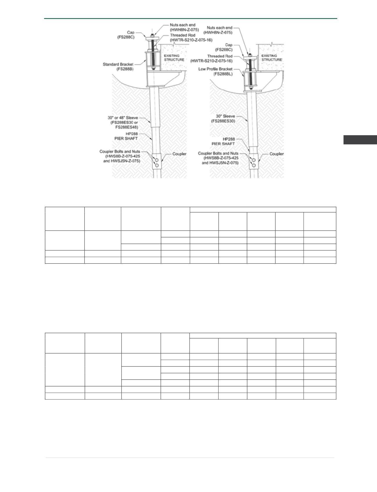
FIGURE 1—HP288 RETROFIT BRACKET AND SHAFT ASSEMBLIES
TABLE 2—HP288 (WITH NEW CONSTRUCTION BRACKETS) ASD COMPRESSION CAPACITIES
7
Bracket Part
No.
1
Bearing Plate
Dimensions
(in)
Minimum
Concrete
Compressive
Strength (psi)
Edge
Distance
"A" (in)
Allowable Compression Capacity (kips)
Bracket
(P1)
2
Shaft (P2)
3
Helix (P3)
4
Soil
(P4)
5
Foundation
System
6
HP288NCB or
HP288NCB-G
6 x 6 x 0.75
2500
3
33.1
60
55
35.5
33.1
≥ 4
44.1
60
55
35.5
35.5
3000
≥ 3
39.7
60
55
35.5
35.5
HP288NCB8
8 x 8 x 0.75
2500
≥ 4
43.1
60
55
35.5
35.5
HP288NCB8-G
8 x 8 x 0.75
2500
≥ 4
46.5
60
55
35.5
35.5
For
SI:
I inch = 25.4 mm, 1 kip = 1000 lbf = 4.448 kN.
1
Part numbers with “G” suffix indicate hot-dip galvanized coating. Part numbers without a “G” suffix indicate plain steel.
2
Bracket capacity is based on localized limit state of concrete bearing only. All other limit states related to the concrete foundation, such as punching
shear, have not been evaluated in this evaluation report.
3
Shaft capacity is applicable only to the foundation systems that are fully braced as described in Section 4.1.3.
4
Helix capacity is based on a single helix plate with outer diameter of 8, 10, 12 or 14 inches (203, 254, 305 or 356 mm).
5
Soil capacity is based on torque correlation per Section 4.1.5 of this report, with piles installed at the maximum torsion rating.
6
Foundation system allowable capacity is based on the lowest of P1, P2, P3 and P4 listed in this table. See Section 4.1.6 for additional requirements.
7
Reduction of plain concrete thickness described in Section 22.4.7 of ACI 318-11 for the 2012 IBC (Section 22.4.7 of ACI 318-08 for the 2009 IBC, and
22.4.8 of ACI 318-05 for the 2006 IBC) is assumed not applicable.
TABLE 3—HP288 (WITH NEW CONSTRUCTION BRACKETS) ASD TENSION CAPACITIES
6
Bracket Part
No.
1
Bearing Plate
Dimensions (in)
Minimum
Concrete
Compressive
Strength (psi)
Edge
Distance
"A" (in)
Allowable Tension Capacity (kips)
Bracket
(P1)
2,7
Shaft (P2)
Helix (P3)
3
Soil
(P4)
4
Foundation
System
5
HP288NCB
or
HP288NCB-G
6 x 6 x 0.75
2500
3
24.3
34.1
55
27.6
24.3
≥ 4
32.4
34.1
55
27.6
27.6
3000
≥ 3
29.1
34.1
55
27.6
27.6
3500
≥ 3
34.0
34.1
55
27.6
27.6
HP288NCB8
8 x 8 x 0.75
2500
≥ 4
34.1
34.1
55
27.6
27.6
HP288NCB8-G
8 x 8 x 0.75
2500
≥ 4
38.2
38.2
55
27.6
27.6
For
SI:
I inch = 25.4 mm, 1 kip = 1000 lbf = 4.448 kN, 1 psi = 6.895 kPa.
1
Part numbers with “G” suffix indicate hot-dip galvanized coating. Part numbers without a “G” suffix indicate plain steel.
2
Bracket capacity is based on localized limit state of concrete bearing only. All other limit states related to the concrete foundation, such as punching
shear, have not been evaluated in this evaluation report.
3
Helix capacity is based on a single helix plate with outer diameter of 8, 10, 12 or 14 inches (203, 254, 305 or 356 mm).
4
Soil capacity is based on torque correlation per Section 4.1.5 of this report, with piles installed at the maximum torsion rating.
5
Foundation system allowable capacity is based on the lowest of P1, P2, P3 and P4 listed in this table. See Section 4.1.6 for additional requirements.
6
Reduction of plain concrete thickness described in Section 22.4.7 of ACI 318-11 for the 2012 IBC (section 22.4.7 of ACI 318-08 for the 2009 IBC, and
22.4.8 of ACI 318-05 for the 2006 IBC) is assumed not applicable.
7
Bolts must be installed in accordance with Sections 3.2.2.2 and 4.2.4 of this report.