


 256 / 365

© 2014 Foundation Supportworks
®
,
Inc.
All Rights Reserved
p 256
APPENDIX 3A
BRACKET SPECIFICATIONS AND CAPACITIES
Chapter 3
Hydraulically-Driven Push Piers
Bracket:
Weldment manufactured from
1
”,
3/8
”,
and
1
” ASTM A36 plate.
Pier Tube:
Ø
2.875” x 0.165” wall x 36” long
Triple-coated in-line galvanized
ASTM A500 Grade C
Yield strength = 50 ksi (min)
Tensile strength = 55 ksi (min)
Pier Tube Coupler:
Ø
2.250” x 0.180” wall x 6” long
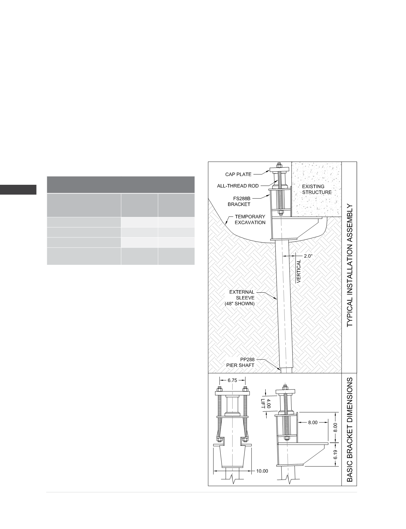
FS288B Bracket Specifications and Capacities
when used with the PP288 Push Pier System
Allowable Bracket Capacity
(4,5,6,7)
R
n
/Ω
with 30”
Sleeve
(kips)
with 48”
Sleeve
(kips)
Plain
23.9
36.7
Plain Corroded
(1)
18.5
28.4
Grout Filled Corroded
(1)
20.9
32.1
Maximum Drive Force
During Installation
(7)
48.1
60.0
(1) Corroded capacities include a 50-year scheduled sacrificial loss
in thickness per ICC-ES AC406. Grout filled piers consider a loss
in thickness at the outside diameter only.
(2)
Hot-dip galvanized coating in accordance with ASTM A123.
(3)
Optional hardware utilizes similar sized contour (coil) thread
made from AISI 1045, tensile strength = 120 ksi. Slightly lower
tensile strength material does not govern the listed capacities.
(4)
Brackets shall be used for support of structures that are
considered to be fixed from translation. Structures that are not
fixed from translation shall be braced in some manner prior to
installing retrofit brackets systems.
(5)
Allowable compression capacities consider continuous lateral soil
confinement in soils with SPT blow counts ≥ 4. Piers with exposed
unbraced lengths or piers placed in weaker or fluid soils should be
evaluated on a case by case basis by the project engineer.
(6)
Concrete bearing assumes a minimum compressive strength
(f’c) of 2,500 psi. Local concrete bending and other local design
checks should be evaluated on a case by case basis by the
project engineer.
(7)
Push Piers shall be installed with a driving force exceeding the
required allowable service load by a sufficient factor of safety
(FOS). FOS is most commonly between 1.5 and 2.0, although
a higher or lower FOS may be considered at the discretion
of the pier designer or as dictated by local code or project
requirements.
Pier Starter Tube:
Pier tube section with machined
Ø
3.375”
friction reduction collar pressed around
leading end.
External Sleeve:
Ø
3.500” x 0.216” wall x 30” or 48” long with
welded collar or trumpet flare at one end.
ASTM A500 Grade B or C
Yield strength = 50 ksi (min)
Tensile strength = 62 ksi (min)
Cap Plate:
1” x 5.00” x 9.00” ASTM A572 Grade 50
with confining ring welded to one side.
Bracket Hardware
(3)
:
(2) -
Ø
3/4
” x 16” long all-thread rod
Grade B7, tensile strength = 125 ksi (min)
Electrozinc plated per ASTM B633
Bracket Finish:
Available plain or hot-dip galvanized
(2)