
© 2014 Foundation Supportworks
®
,
Inc.
All Rights Reserved
p 251
Chapter 3
Hydraulically-Driven Push Piers
CHAPTER 3
HYDRAULICALLY-DRIVEN PUSH PIERS
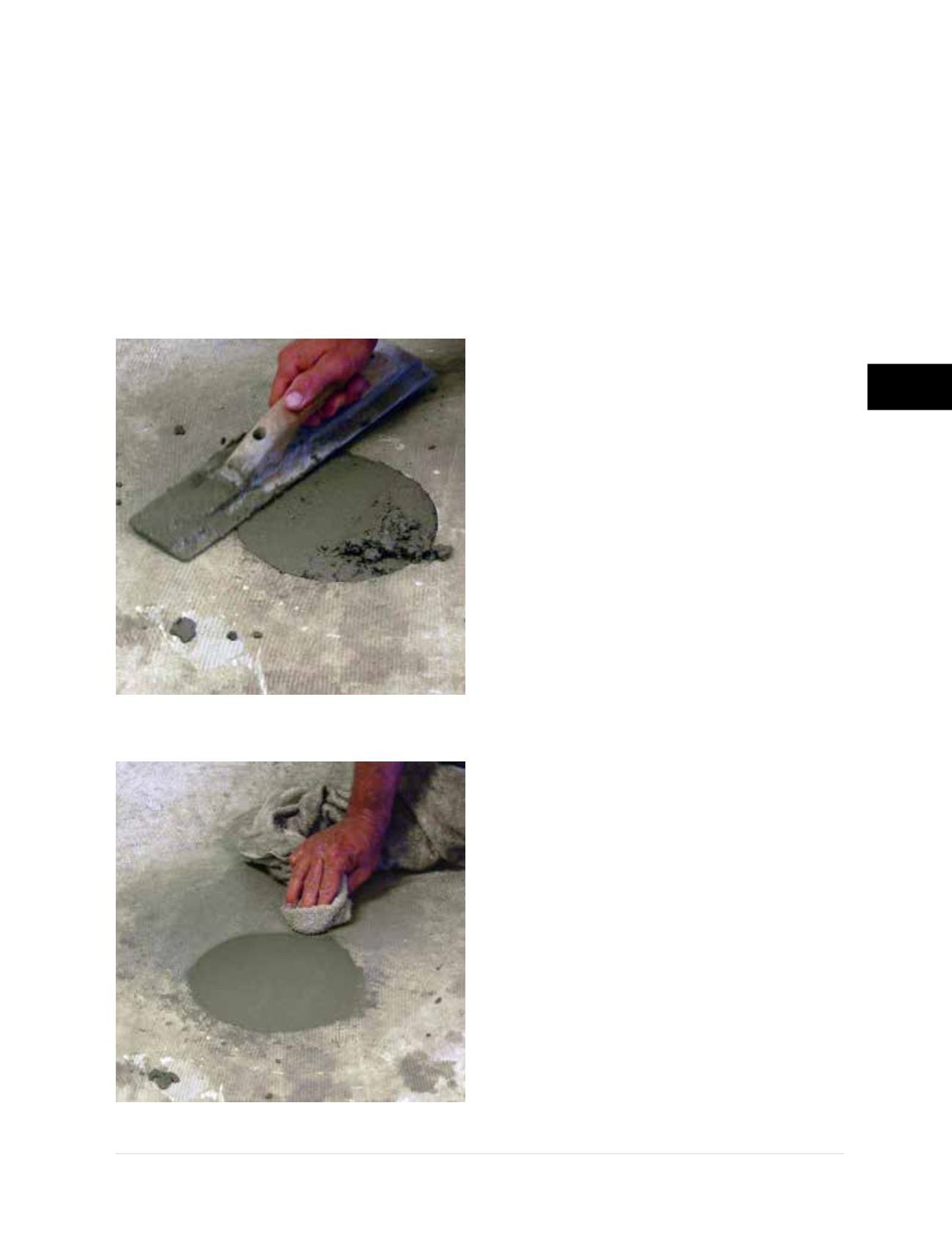
Step 7 Void Fill and Finish Surface
• Place concrete and trowel finish at each pier
location
(Figures 3.12.u and 3.12.v)
. Voids
under the slab should be filled completely with
grout or PolyLEVEL
®
polyurethane foam. Void
filling is typically completed before patching
the core holes with concrete, but can be done
either before or after the concrete is placed.
Concrete patches should be allowed to cure
before void filling.
3.13 Push Pier Load Testing
The push pier installation process is essentially
equivalent to performing a proof load test at each
push pier location and, therefore, prescribed
“official” load testing of push pier systems is
not common. The piers are advanced to a drive
or ultimate load, then reloaded to the specified
lock-off load (typically at or near the service
load) or until the desired lift is achieved. The
drive and lock-off loads are easily calculated
from the effective area of the hydraulic cylinder
and the pressure gauge reading at the hydraulic
pump. Pile head movements are not typically
monitored during the proof loading process of a
typical push pier installation.
The deflection to load response of the push pier
system can be determined by field load testing
using calibrated equipment either directly at
the bracket location or with sacrificial piers
installed away from the structure. The loading
methodology in ASTM D1143 may be used to
verify pier deformation (elastic compression and
settlement) and creep effects. The preferred
method is to perform the load test at the bracket
location with the bracket attached to the
structure. If a sacrificial test pier is used away
from the structure, a compression load test
frame must be constructed.
Figure 3.12.u
Patching holes at pier locations
Figure 3.12.v
Finishing concrete


