


 295 / 365

© 2014 Foundation Supportworks
®
,
Inc.
All Rights Reserved
p 295
Chapter 4
Miscellaneous Structural Support Products
CHAPTER 4
MISCELLANEOUS STRUCTURAL SUPPORT PRODUCTS
to the threads on the rod which significantly
reduces friction between the rod and nut and
results in a higher applied force than nuts
tightened to similar torque in a dry condition. The
average applied force noted in
Figure 4.2.4.2.a
was generated from dozens of test samples with
testing completed at an independent test facility.
Due to product variations, these values should
only be considered applicable to products
supplied by Foundation Supportworks.
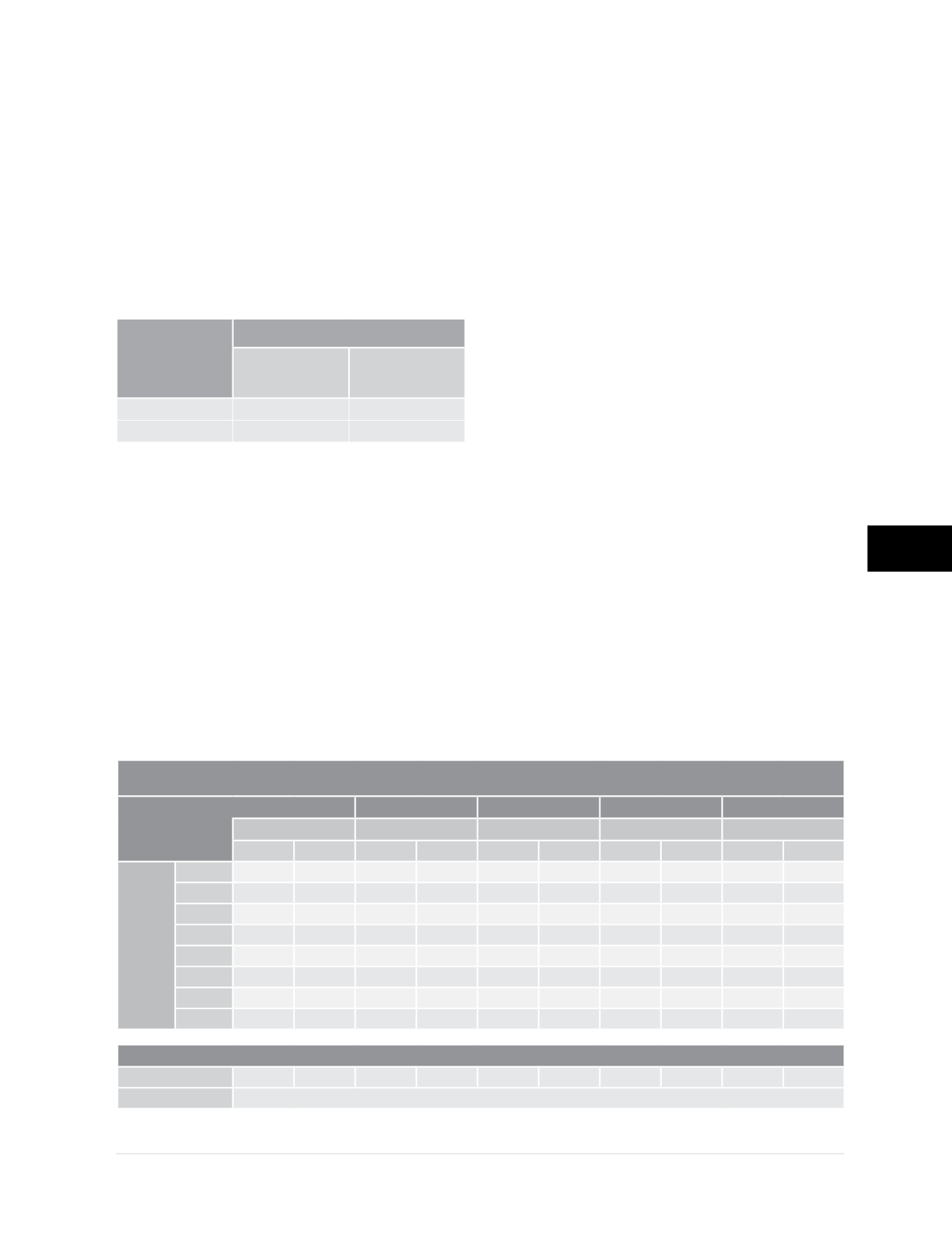
Applied Torque
(ft-lb)
Average Applied Force (lb)
Waxed
Condition
Dry Condition
80
11,900
6,100
90
12,900
6,900
Figure 4.2.4.2.a
Average applied force on the anchor rod versus
applied torque on the anchor rod nut
Installers shall closely monitor the tightening
process of the wall anchor installation and
reduce the applied torque as necessary for
atypical conditions.
4.2.4.3 Depth and Location of Earth
Anchor
The Geo-Lock Wall Anchor System is designed
with two (2) -inch diameter, 80-inch long all-
thread rods coupled together. This total rod length
of 13 feet 4 inches allows the earth anchor to be
approximately 12 feet from the stabilized wall, far
enough to prevent load from the anchor being
transferred back to the wall. Considering the
backfill height, the vertical placement of the earth
anchor, and a range of soil types and strengths,
the coupled rod length of 13 feet 4 inches would
be adequate for typical applications with backfill
heights up to about 8 feet. Additional all-thread
rod sections can easily be added as necessary
for backfill heights greater than 8 feet.
The following tables provide the horizontal
location of the earth anchor from the exterior face
of the foundation wall (Ah) and the earth anchor
depths (Avt and Avb) considering a variety of soil
conditions. Refer to
Figure 4.2.1.a
when using
these tables. One quickly observes that soil type
has little effect and changes Ah and Avb only
slightly. Rather, values of Ah and Avb are driven
more by minimum depth criteria and geometry.
Soil Description: Medium Dense Sand and Gravel
Internal angle of friction (
Φ
) = 34 degrees
“Ah” Minimum Required Horizontal Location to Anchor (ft)
“Pv” Depth Below
Grade to Center of
Wall Plate (ft)
1
2
3
4
5
Anchor Size
Anchor Size
Anchor Size
Anchor Size
Anchor Size
Small
Med/Lrg Small
Med/Lrg Small
Med/Lrg Small
Med/Lrg Small
Med/Lrg
“F” Unbalanced
Fill Depth (ft)
10
12.2
13.0
12.2
13.0
13.0
13.8
14.9
15.7
16.8
17.5
9
11.7
12.5
11.7
12.5
12.5
13.2
14.4
15.1
8
11.2
11.9
11.2
11.9
11.9
12.7
13.8
14.6
7
10.6
11.4
10.6
11.4
11.4
12.2
6
10.1
10.9
10.1
10.9
10.9
11.7
5
9.6
10.3
9.6
10.3
4
9.0
9.8
9.0
9.8
3
8.5
9.3
“Avb & Avt” Minimum Required Depths Below Grade to Anchor (ft)
Bottom - Avb:
3.7
4.1
3.7
4.1
4.1
4.5
5.1
5.5
6.1
6.5
Top - Avt:
Depth as needed to prevent frost effects