


 298 / 365

© 2014 Foundation Supportworks
®
,
Inc.
All Rights Reserved
p 298
Chapter 4
Miscellaneous Structural Support Products
CHAPTER 4
MISCELLANEOUS STRUCTURAL SUPPORT PRODUCTS
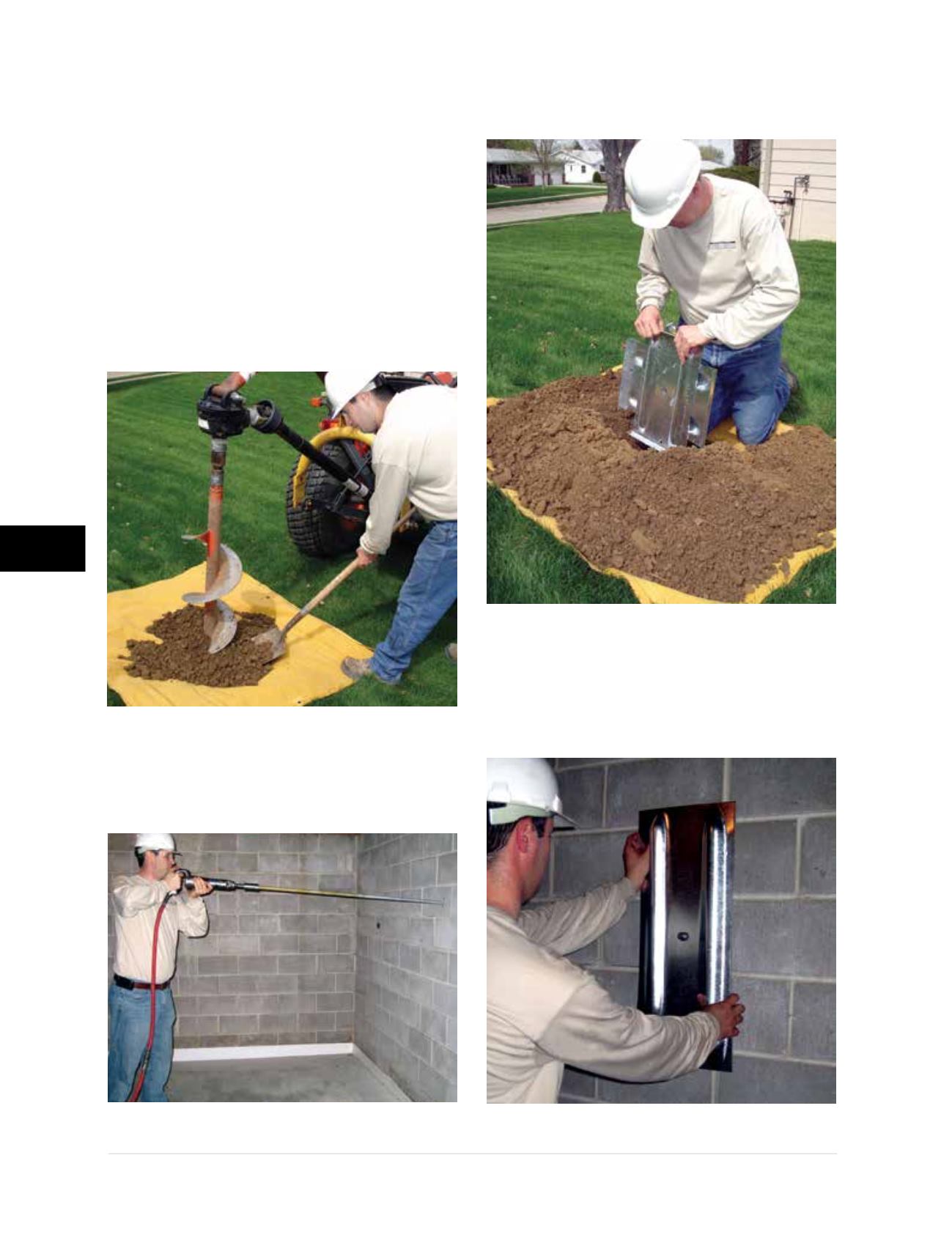
4.2.5 Installation Steps
The following steps provide a broad overview
of a typical Geo-Lock Wall Anchor System
installation. Intermediate steps, installation
equipment and tools used, and considerations
for unusual conditions or applications are not
addressed.
Step 1
– Sod is carefully removed and a hole is
excavated or augered
(Figure 4.2.5.a1)
. The front
face of the hole (toward structure) is cut flat to
accept the earth anchor.
Step 2
– A small 1
1/8
-inch hole is drilled through
the basement wall and the anchor rod is driven out
to penetrate the augered hole
(Figure 4.2.5.a2)
.
Step 3
– Earth anchor is placed in the augered hole
and attached to the anchor rod
(Figure 4.2.5.a3)
.
Step 4
- Interior wall plate is positioned over the
anchor rod and tightened to the specified torque,
seating the earth anchor and engaging the
passive resistance of the soils
(Figure 4.2.5.a4)
.
Figure 4.2.5.a1
Figure 4.2.5.a2
Figure 4.2.5.a3
Figure 4.2.5.a4