


 327 / 365

© 2014 Foundation Supportworks
®
,
Inc.
All Rights Reserved
p 327
APPENDIX 4D
SMARTJACK® SYSTEMS
Chapter 4
Miscellaneous Structural Support Products
Design Example
Step 1
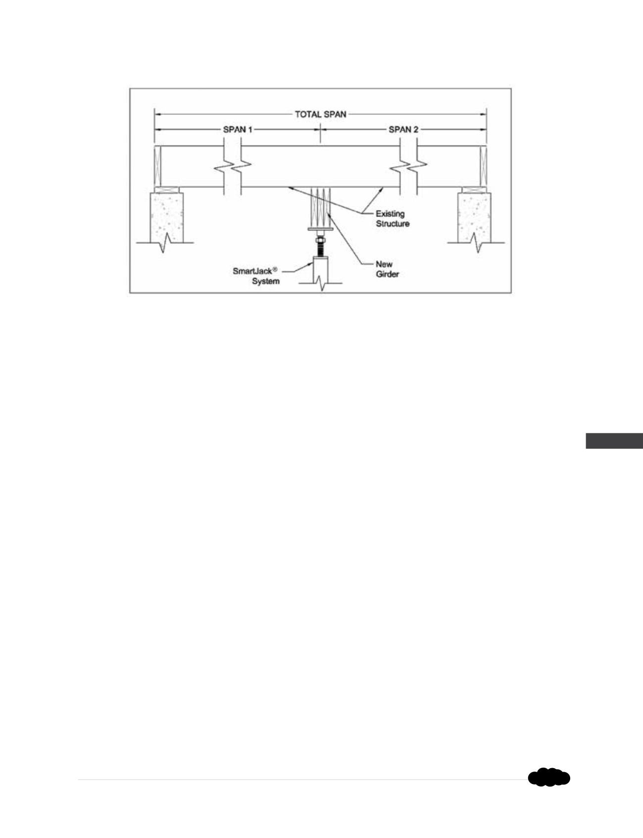
- Determine the load which will be supported by the girder in pounds per linear foot:
Girder Load (plf) = (Span 1 (ft) + Span 2 (ft)) x Floor Load (psf) ÷ 2
Note 1:
Typical residential wood-framed construction may have an approximate floor load (dead
load + live load) = 55 psf
Note 2:
This equation assumes a floor system which does not support any load bearing walls or
columns.
Step 2
- Determine the load on the SmartJacks
®
by multiplying the calculated Girder Load (plf) by the
spacing of the SmartJacks
®
:
SmartJack Load (lbs) = Girder Load (plf) x SmartJack
®
Spacing (ft)
Step 3
- Verify that the calculated SmartJack
®
load is less than the allowable capacity provided by the
various system components as well as the well-compacted crushed stone base and the bearing soils.
Note 3:
Without a detailed soil investigation, typical installations should assume no more than
1,500 psf allowable soil bearing pressure. This would equate to an allowable soil capacity of
6,000 lbs for a 2’x2’ poured concrete footing or a 2’ cube of well-compacted crushed stone.
Extremely soft soils may prohibit the use of a crushed stone base or require that a larger poured
concrete footing be utilized.
Step 4
- Size the new girder by entering the following table with both the SmartJack
®
Spacing (ft)
and the calculated Girder Load (plf). Choose a girder that has an Allowable Load (plf) greater than the
calculated Girder Load (plf).
Rev. 9/23/15