


 332 / 365

© 2014 Foundation Supportworks
®
,
Inc.
All Rights Reserved
p 332
APPENDIX 4D
SMARTJACK® SYSTEMS
Chapter 4
Miscellaneous Structural Support Products
Step 3
- Verify that the calculated SmartJack
®
load is less than the allowable capacity provided by the
various system components as well as the well-compacted crushed stone base and the bearing soils.
Note 3:
Without a detailed soil investigation, typical installations should assume no more than
1,500 psf allowable soil bearing pressure. This would equate to an allowable soil capacity of
6,000 lbs for a 2’x2’ poured concrete footing or a 2’ cube of well-compacted crushed stone.
Extremely soft soils may prohibit the use of a crushed stone base or require that a larger poured
concrete footing be utilized.
Step 4
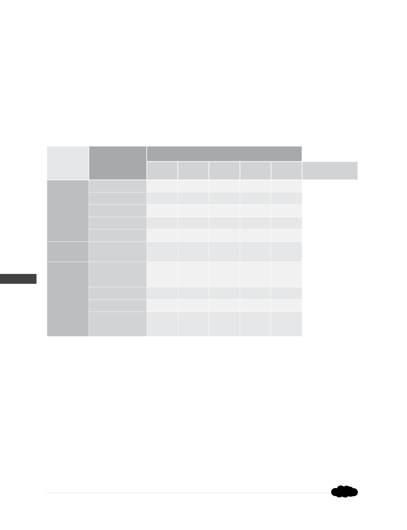
- Size the new girder by entering the following table with both the SmartJack
®
Spacing (ft)
and the calculated Girder Load (plf). Choose a girder that has an Allowable Load (plf) greater than the
calculated Girder Load (plf).
Girder Size
Girder Allowable Load (plf)
(1,2,3)
4 ft
5 ft
6 ft
7 ft
8 ft
SmartJack
®
Spacing
Sawn
Lumber
(4)
(3) – 2 x 8
1,170
750
520
380
290
(3) – 2 x 10
1,760
1,120
780
570
440
(3) – 2 x 12
2,360
1,510
1,050
770
590
(1) – 4 x 6
850
550
380
280
210
(1) – 6 x 6
1,030
660
460
330
250
Engineered
Lumber
(5)
3.5 x 5.5
1,250
740
420
270
180
Structural
Steel
(6)
S4 x 7.7
(PowerBrace
™
Beam)
3,780
2,070
1,200
750
500
W4 x 13
6,820
3,850
2,240
1,400
940
HSS 4 x 4 x
1
5,190
2,650
1,530
960
640
HSS 4 x 2 x
1
(Lying Flat in Plank
Orientation)
990
500
290
180
120
(1)
This table makes no evaluation of the components of the existing structure.
(2)
Allowable loads in this table assume the girder is sufficiently restrained against lateral torsional buckling at an interval equal to or less than
the SmartJack
®
spacing.
(3)
The new girder may be cantilevered over the end support by a distance of 30 inches or by a distance of approximately 40% of the adjacent
SmartJack
®
spacing, whichever is less.
(4)
Sawn lumber is assumed to be Douglas Fir Larch - No. 2 or better.
(5)
Engineered lumber is assumed to be iLevel 1.3E TimberStrand LSL or equivalent.
(6)
Structural steel is assumed to be ASTM A572 Grade 50 or equivalent for wide flange shapes, and ASTM A500 Grade B or equivalent for
HSS tube shapes.
Step 5
- If the required girder size is undesirable, adjust spacing of the SmartJacks
®
and return to
Step 2.
Rev. 9/23/15