
© 2014 Foundation Supportworks
®
,
Inc.
All Rights Reserved
p 331
APPENDIX 4D
SMARTJACK® SYSTEMS
Chapter 4
Miscellaneous Structural Support Products
The SmartJack
®
is designed to support axial compression loads only. The SmartJack
®
should
not be used in applications where the system is intended to resist lateral loads.
Corrosion Protection
The tube steel used for the SmartJack
®
is manufactured with a triple-layer, in-line galvanized coating.
This coating process consists of: (1) a uniform hot-dip zinc galvanizing layer; (2) an intermediate
conversion coating to inhibit the formation of white rust and enhance corrosion resistance; and (3) a
clear organic top coating to further enhance appearance and durability. The inside of the pier tube
also has a zinc-rich coating.
The cast aluminum base is far less susceptible to corrosion than the steel components that
surround it. There are, however, chlorides in some concrete that can be reactive with aluminum. It is
recommended that a 20 mil x 16” square inert membrane be placed under or around the aluminum
base to seperate it from recycled or poured concrete. Crushed limestone or other crushed stone
alternatives do not have similar considerations.
The remaining steel components of the SmartJack
®
system come standard as electrozinc plated per
ASTM B633.
Design Example
Step 1
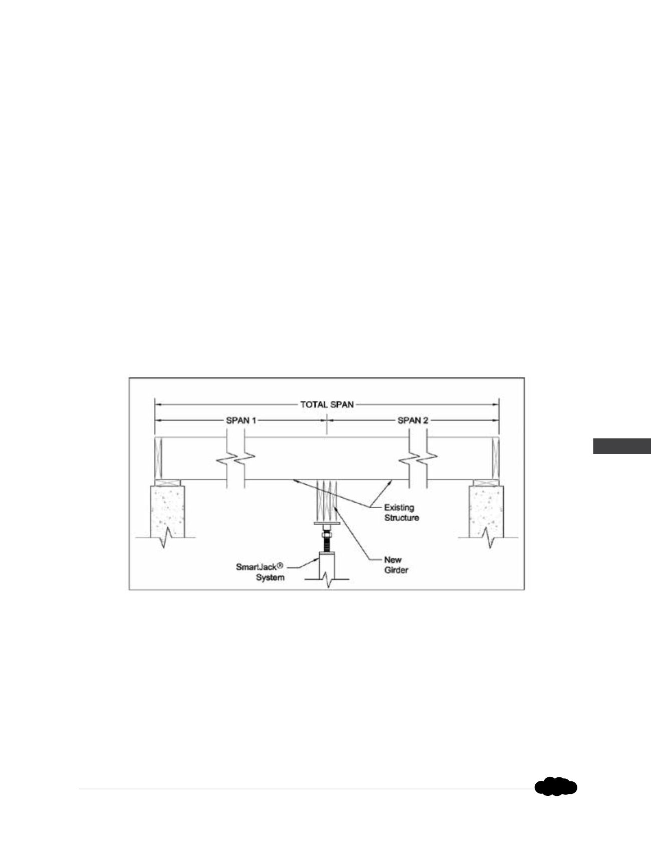
- Determine the load which will be supported by the girder in pounds per linear foot:
Girder Load (plf) = (Span 1 (ft) + Span 2 (ft)) x Floor Load (psf) ÷ 2
Note 1:
Typical residential wood-framed construction may have an approximate floor load (dead
load + live load) = 55 psf
Note 2:
This equation assumes a floor system which does not support any load bearing walls
or columns.
Step 2
- Determine the load on the SmartJacks
®
by multiplying the calculated Girder Load (plf) by the
spacing of the SmartJacks:
SmartJack Load (lbs) = Girder Load (plf) x SmartJack
®
Spacing (ft)
Rev. 9/23/15


