


 41 / 365

© 2014 Foundation Supportworks
®
,
Inc.
All Rights Reserved
p 41
Chapter 2
Helical Foundation Systems
CHAPTER 2
HELICAL FOUNDATION SYSTEMS
2.11 Design Examples
Three common methods for determining helical
pile capacity are presented in Section 2.7. The
individual bearing and cylindrical shear methods
are used during the design phase to calculate or
estimate the pile capacity. The torque correlation
method is generally used to confirm or verify pile
capacity during field installation. FSI promotes
the use of the individual bearing method for
design calculations, therefore, that method
will be used in the following examples. Helical
pile product ratings, properties and details are
provided in Appendix 2A.
HelixPro
®
Helical Foundation Design Software
for Professionals was created by Foundation
Supportworks to simplify the design process
for helical piles and tiebacks. HelixPro is a
web-based helical foundation design tool
available free of charge to design professionals.
For more information on HelixPro, please refer
to Appendix 2C.
2.11.1 Helical Piles
Example 1
Helical piles are proposed to support a new
structure. The proposed pile layout is shown
on the foundation plan along with a design
working load of 30 kips per pile with a factor of
safety (FOS) = 2. Preliminary product selection
suggests that the HP288 helical pile is the best
fit for this load condition with an ultimate torque
rated capacity of 71.1 kips. The allowable torque
rated capacity would then be 35.5 kips with a
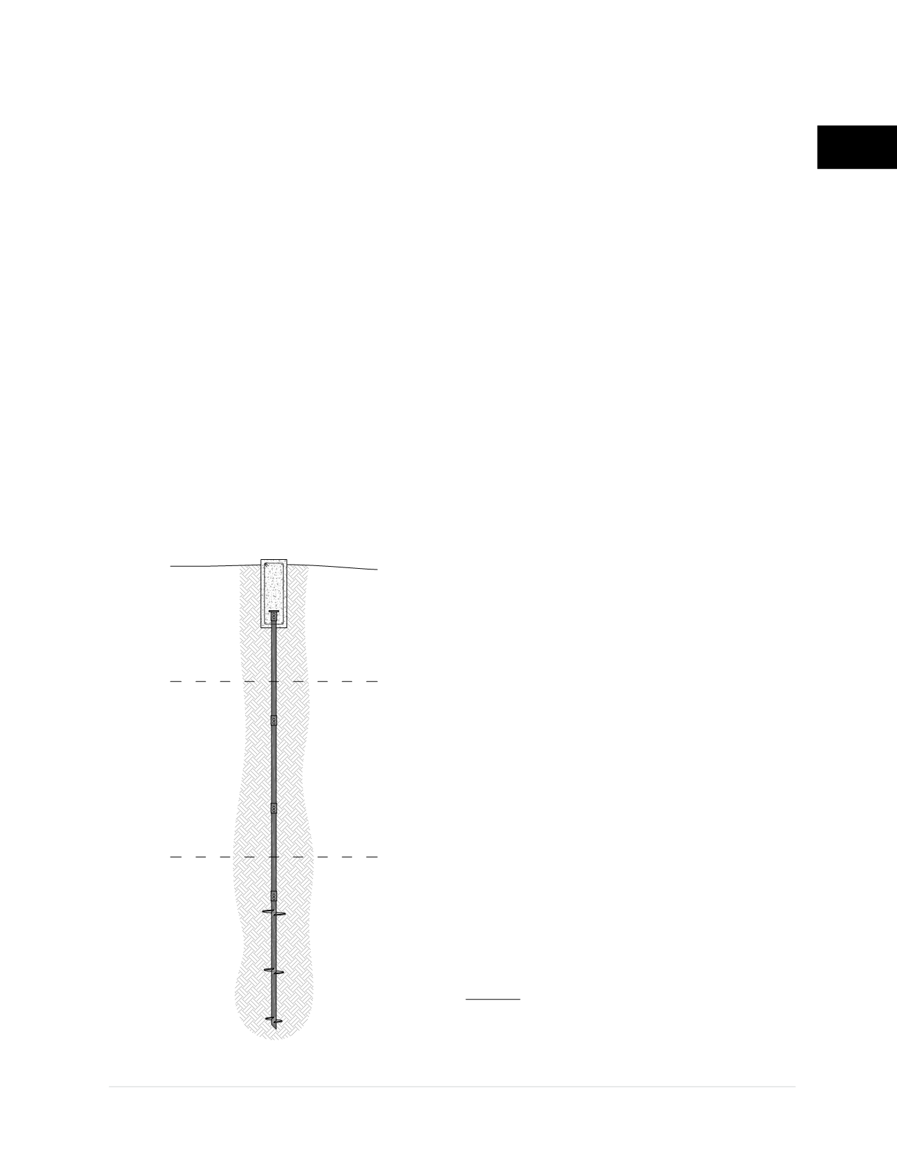
FOS = 2. A geotechnical investigation was
completed for the project and the soil profile is
shown in
Figure 2.11.1.a
.
The helical piles will penetrate the upper fill and
medium stiff clay to bear within the deeper very
stiff clay. With the helix plates bearing entirely
within the very stiff clay soil below a depth of 15
feet, we can use the equation from Section 2.7.1
for purely cohesive soils with
Φ
= 0:
Q
u
= ∑A
h
(9c)
Solve for the required helix plate area:
A
h
= Q
u
/9c
Q
u
= Design Working Load (30,000 lb) x FOS
(2) = 60,000 lb
c
= 3,000 lb/ft
2
A
h
= 60,000 / (9)(3,000)
A
h
= 2.22 ft
2
Helix plate areas for the various shaft sizes can
be found in Appendix 2A. For the HP288 shaft
(2.875-inch O.D.), a total helix plate area of
2.22 ft
2
can be most efficiently achieved with a
10/12/14 triple-helix plate configuration.
A
10”
= 0.50 ft
2
A
12”
= 0.74 ft
2
A
14”
= 1.02 ft
2
∑A
h
= 2.26 ft
2
Figure 2.11.1.a
Example 1. Helical Pile Capacity
Loose Sand Fill
(Highly Variable)
6’
Medium Stiff Clay
c= 750 lb/ft
2
Φ = 0
γ
moist
= 115 Ib/ft
3
15’
Very Stiff Clay
c= 3,000 lb/ft
2
Φ = 0
γ
moist
= 120 Ib/ft
3