


 44 / 365

© 2014 Foundation Supportworks
®
,
Inc.
All Rights Reserved
p 44
Chapter 2
Helical Foundation Systems
CHAPTER 2
HELICAL FOUNDATION SYSTEMS
2.11.2 Helical Tiebacks
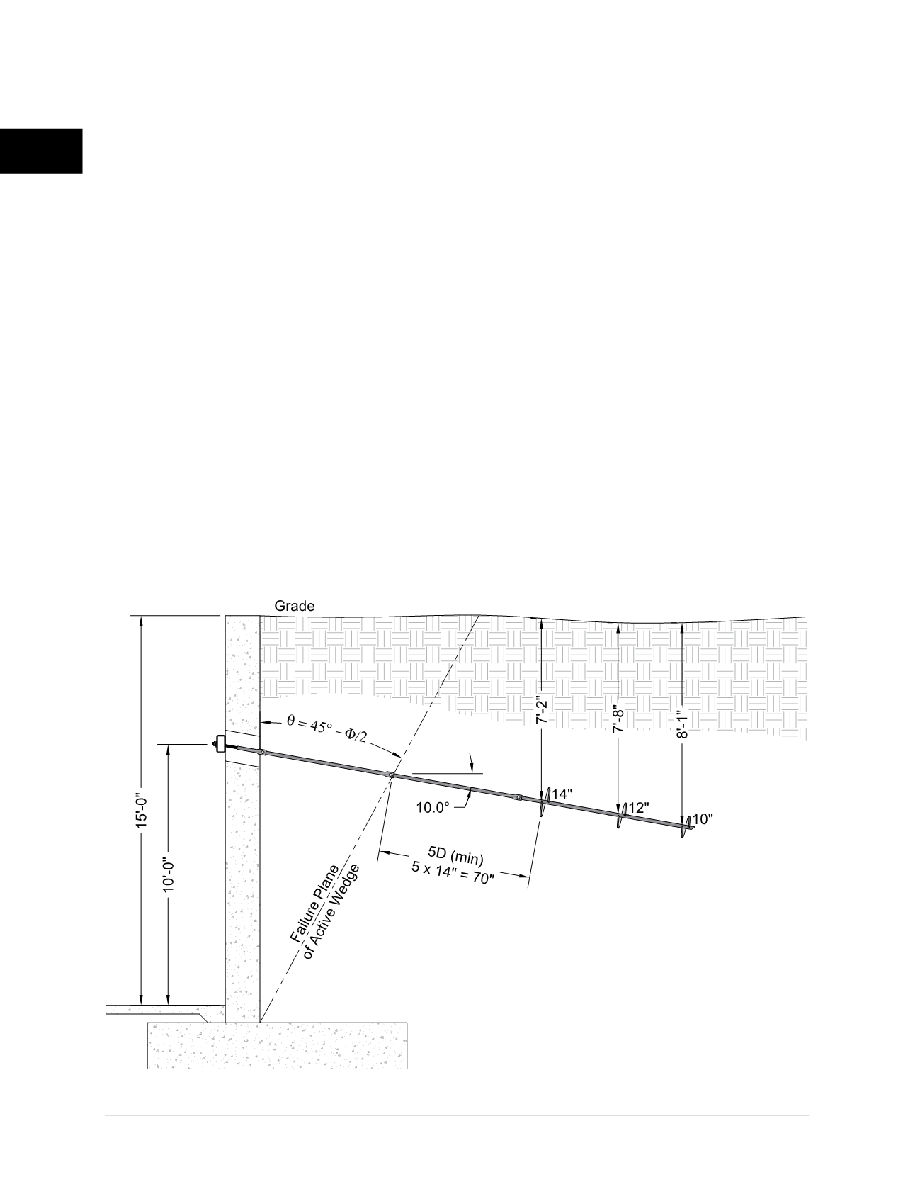
Example 3
Helical tiebacks are being considered to stabilize
an existing reinforced concrete retaining wall.
The tiebacks can extend no further than 20 feet
from the front face of the wall due to property
line issues. A geotechnical investigation found
the retained soils to consist of silty sand. The
design engineer proposed an HA150 shaft
(1.5-inch solid square) with a 10/12/14 helix
plate configuration. The soil parameters and
preliminary tieback design are shown on
Figure
2.11.2.a
. The engineer must determine the
allowable tieback capacity so tieback spacing
can be established.
Q
u
= ∑A
h
(q’N
q
)
A
14”
= 1.05 ft
2
A
12”
= 0.77 ft
2
A
10”
= 0.53 ft
2
q’
14”
= (120)(7.17) = 860 lb/ft
2
q’
12”
= (120)(7.67) = 920 lb/ft
2
q’
10”
= (120)(8.08) = 969 lb/ft
2
N
q
= 1+0.56(12
Φ
)
Φ
/54
= 15.7
Q
u
= (1.05)(860)(15.7) + (0.77)(920)(15.7) +
(0.53)(969)(15.7) = 33,300 lb = 33.3
kips
Q
a
= 33,300 / 2 (FOS) = 16,650 lb = 16.6 kips
The horizontal and vertical components of the
tieback force can be calculated in accordance
with Section 2.8.1.
Figure 2.11.2.a
Example 3. Helical Tieback Capacity
Retained Soils:
Silty Sand
c= 0
Φ = 30°
γ
moist
= 120 Ib/ft
3