


 42 / 365

© 2014 Foundation Supportworks
®
,
Inc.
All Rights Reserved
p 42
Chapter 2
Helical Foundation Systems
CHAPTER 2
HELICAL FOUNDATION SYSTEMS
Solve for the ultimate and allowable pile
capacities:
Q
u
= (2.26)(9)(3,000) = 61,000 lb = 61 kips
The allowable pile capacity,
Q
a
= Q
u
/ FOS
Q
a
= 61,000 / 2 = 30,500 lb = 30.5 kips…OK
Determine the required final installation
torque in accordance with the equations and
procedures of Section 2.7.3:
Q
u
= K
t
T
The equation can be rewritten to solve for torque:
T = Q
u
/ K
t
Without site-specific load testing and
determination of K
t
, we use the default value
from ICC-ES AC358 for a 2.875-inch O.D.
shaft, K
t
= 9 ft
-1
:
T
= 60,000 / 9 = 6,667 ft-lb
Install the helical piles to a final installation
torque of at least 6,700 ft-lb.
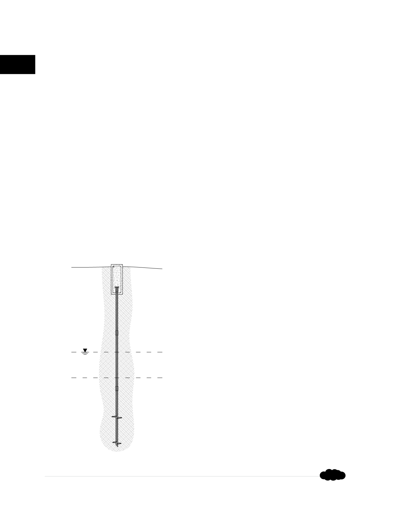
Example 2
Grain conveyor towers will be constructed at
an ethanol facility. The towers will be designed
with four support legs, each leg designed for
working loads of 40 kips in compression and 15
kips in tension/uplift. A FOS = 2 is required for
both the compression and uplift pile capacities.
A geotechnical exploration was completed
for the project and the soil profile is shown in
Figure 2.11.1.b
. Groundwater was encountered
at a depth of 10 feet below the surface.
Preliminary product selection suggests that the
HP350 helical pile is best suited to support the
proposed loads. The HP350 has an ultimate
torque rated capacity of 122.5 kips and an
allowable capacity of 60 kips (FOS = 2.04; see
footnote 7 on page 61). Allowable mechanical
compression and tension capacities are well
above the service loads to be resisted. The
helical piles will be embedded into the dense
sand as shown in
Figure 2.11.1.b
.
For purely granular (frictional) soils with c = 0,
the ultimate pile capacity can be determined
from equation:
Q
u
= ∑A
h
(q’N
q
)
Solve for the required helix plate area:
A
h
= Q
u
/q’N
q
The helix plates should be embedded several
plate diameters into the dense sand to provide
uplift resistance. This depth depends upon the
pile load. We can fine tune the embedment
depth at a later point, but for an uplift load of
15 kips, we’ll consider a minimum helix plate
embedment of three diameters. A pile with an
ultimate capacity of 80 kips often has three helix
plates on the lead section. A 10/12/14 lead has
a distance of 5.5 feet between the uppermost
and bottommost plates. With these parameters
in mind, we’ll choose a trial depth of:
13 feet + 3.5 feet (depth of 14-inch plate into
dense sand) + 2.75 feet (half the distance
between bearing plates) = 19.5 feet.
Figure 2.11.1.b
Example 2. Helical Pile Capacity
Groundwater
Table
10’
Loose Sand
c= 0
Φ = 30°
γ
moist
= 110 Ib/ft
3
γ
sat
= 115 Ib/ft
3
13’
Dense Sand
c= 0
Φ = 38°
γ
moist
= 120 Ib/ft
3
γ
sat
= 130 Ib/ft
3
Rev. 10/14/16