


 37 / 365

© 2014 Foundation Supportworks
®
,
Inc.
All Rights Reserved
p 37
Chapter 2
Helical Foundation Systems
CHAPTER 2
HELICAL FOUNDATION SYSTEMS
The design procedure for helical soil nails is
similar to that for grouted nails. For a helical soil
nail, the bond stress with the soil is assumed
to act along a cylindrical surface area defined
by the outside edge of the helix plates. Bearing
capacity of the soil nail is determined using the
Individual Bearing Method described in Section
2.7 and is correlated to bond stress by:
q
u
= Q
u
/ LπD
h
FS
Where,
q
u
= Ultimate Bond Stress (psi)
Q
u
= Ultimate Capacity of the Helical Soil Nail
by Individual Bearing Method (lb)
L
= Soil Nail Length (in)
D
h
= Helix Diameter (in)
FS
= Factor of Safety for Uncertainties in Soil
Conditions (Typically 1.5 to 2.0 Based on
Quality of Soil Information)
As the construction of the wall progresses, the
upper soil nails become less important for the
stabilization of the soil mass, and depending
upon wall height, may not contribute to the global
stability at the final excavation phase. However,
the upper soil nails are instrumental in providing
stability during the early phases of excavation
and contribute to limiting wall deflections.
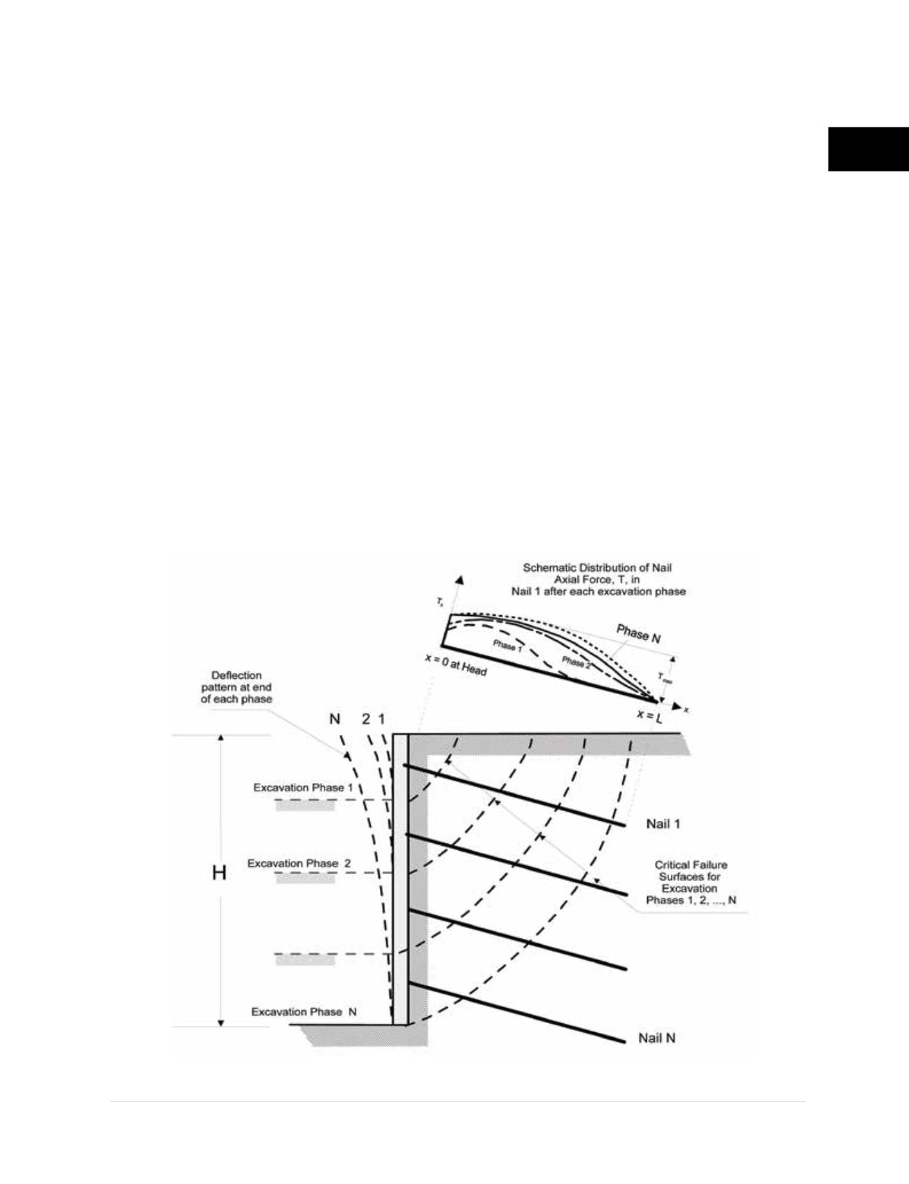
Figure
2.9.2.a
shows the distribution of tensile force in
Nail 1, cumulative wall movement and the critical
failure surfaces as the soil nail wall construction
progresses. The upper schematic of
Figure
2.9.2.a
illustrates the tensile force distribution
along the top soil nail as construction continues
through the various excavation phases. Phase
N in the upper schematic does not reflect the
maximum soil nail tensile force since additional
loading occurs after construction to reach long
term equilibrium of soil nail forces.
The design of helical soil nail walls should
be performed in general accordance with
Figure 2.9.2.a
Potential failure surfaces and soil
nail tensile forces
(Lazarte, Elias et al. 2003)