


 121 / 365

© 2014 Foundation Supportworks
®
,
Inc.
All Rights Reserved
p 121
APPENDIX 2C
HELIXPRO
®
HELICAL FOUNDATION DESIGN SOFTWARE FOR PROFESSIONALS
Chapter 2
Helical Foundation Systems
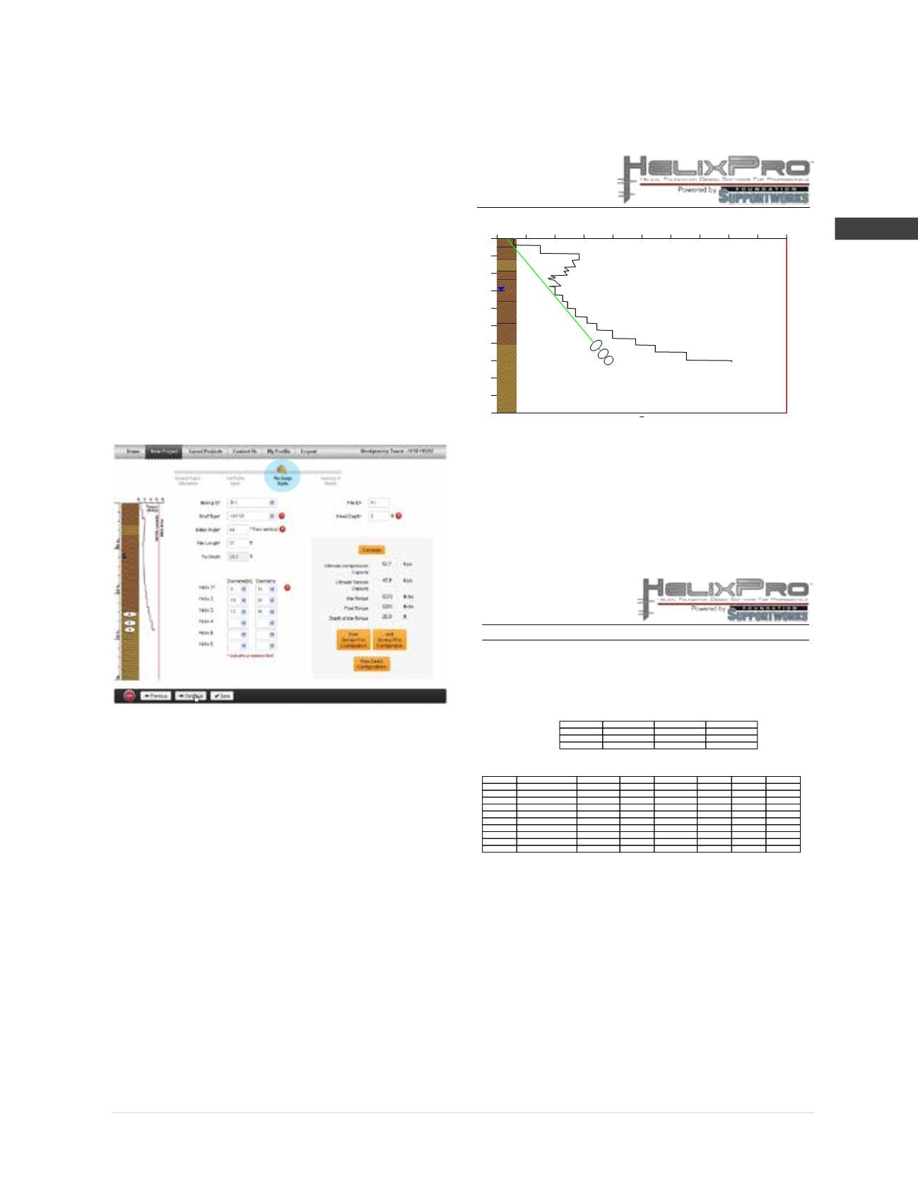
have been filled, pile capacity is determined by
the program by clicking the “Calculate” button.
The ultimate tension and compression capacity,
maximum installation torque, final installation
torque and depth to maximum installation
torque are calculated and displayed. Installation
torque versus depth is displayed graphically
next to the soil profile. Multiple pile types can
be entered and saved.
An ultimate tension capacity of 45.9 kips is
determined for the HA150 (1.5-inch round
corner square bar) with an 8”-10”-12” helix
plate configuration, a 40 degree batter, 37
feet of installed length and the soil conditions
represented by Boring B-1.
Step 6
Continuing to the
Summary of Results
page allows the user to select the boring/pile
combinations to include in the final report, and
also the order in which to present the results.
Output reports are generated in PDF format for
each boring/pile (pile module) or each boring/
wall/tieback row (tieback module). The reports
are formatted to include all of the input data, the
calculated results and other design information
needed for project submittals. A graphical
representation of the soil profile, helical pile
batter and depth, and installation torque with
depth is created. For the tieback module, the
graphical representation also includes the wall
and failure plane geometry.
If you have any questions regarding the
software, please feel free to contact FSI through
the Contact Us page of the software.
The engineers at Foundation Supportworks
®
, Inc.
utilize HelixPro every day to prepare preliminary
design recommendations for design professionals
and our contractor network. We are confident
that you will also find HelixPro to be a valuable
tool for your design of helical foundations.
Register now to use this FREE state-of-the-art
software program by going to
www.helixpro.
foundationsupportworks.com.
Within
two
working days, you should receive an email
stating that your account has been activated. No
gimmicks. No strings attached.
PreparedBy:
CompanyName:
DonDeardorff
FoundationSupportworks
ProjectName:
ProjectNumber:
Date:
MontgomeryTower
FSI #11257
September 26, 2012
Application:
HelicalPiles
Boring ID/Pile ID:
B-1/P1
ShaftType:
HA150
HeadDepth:
0 ft
BatterAngle:
40°
PileLength:
37 ft
TipDepth:
28.3 ft
Diameter (in)
Geometry
Depth (ft)
Helix1
8
H
27.9
Helix2
10
H
26.4
Helix3
12
H
24.5
UltimateCompressionCapacity:
52.7 kips
UltimateTensionCapacity:
45.9 kips
Final InstallationTorque:
5,265 ft-lbs
Maximum InstallationTorque:
5,270 ft-lbs
Depth atMaxTorque:
28.0 ft
GroundwaterDepth:
12 ft
CriticalDepth:
20 ft
Depth
SoilType
SPT 'N'Value C (psf)
eff. (pcf)
deg
Nc
Nq
γ
φ
0
Clay
10
1250
100
0
9
0
2
Clay
10
1250
100
0
9
0
5
Mixed
16
0
112
28.4
22
13
7.5
Clay
6
750
92
0
9
0
9.5
Clay
8
1000
96
0
9
0
12
Clay
8
1000
53
0
9
0
14.5
Clay
11
1375
54
0
9
0
19.5
Clay
17
2125
58
0
9
0
24.5
Mixed
30
0
70
31.9
30
19.8
29.5
Mixed
100
0
72
49.3
163
191.1
Refer to the latest version of theFSITechnicalManual for appropriate termination devices including threaded rod adapters, retrofitbrackets andnew
constructionbrackets. Theapplication anddesign of termination devices should be confirmed by thedesign professional of record.
FSI helical pile and tieback lead sections aremanufactured in true lengths of 5, 7 and 10 feet. FSI helicalextension sections have nominal lengths of
3, 5, 7and 10 feet. Thesenominal lengthsare the truemeasured lengths forHP349,HP350 andHP450 shafts, and are the net lengths (total length
minus coupler overlap) forHA150 andHA175 shafts. The net lengths forHP287andHP288 extension shafts are 6 inches less than the nominal
lengths. Helical leads and extensions are available in other non-standard lengths upon request.
FSI helical piles featurehelix platesmanufacturedwitha helix shape conforming to the geometry criteria of ICC-ESAC358. A helix plate thickness of
3/8-inch is standard for plate diametersof 6 to 14 inches. A helix plate thicknessof 1/2-inch is standard for a plate diameter of16 inches. A plate
steel yield strength of at least36 ksi (A36) is standard for theHA150 shaft,while aplate steel yield strength of at least 50 ksi (Grade50) is standard for
HA175,HP287,HP288,HP349,HP350 andHP450 shafts.
FSI offers helical piles and tiebacksas either black (uncoated) steel or as hot-dip galvanized inaccordancewithASTMA123. Hardware is provided as
hot-dip galvanized (ASTMA153),mechanically-galvanized (ASTMB695)or zinc-plated (ASTMB633).
Boring ID/Pile ID:
B-1/P1
Torque (ft-lbs)
0
650
1300
1950
2600
3250
3900
4550
5200
5850
6500
Depth (ft)
0 4 8
12
16
20
24
28
32
36
40
1
2
3
HA150RatedCapacity
Torque