


 224 / 365

© 2014 Foundation Supportworks
®
,
Inc.
All Rights Reserved
p 224
Chapter 3
Hydraulically-Driven Push Piers
CHAPTER 3
HYDRAULICALLY-DRIVEN PUSH PIERS
3.3. Push Pier
System Components
FSI push pier system components are
manufactured to high quality control standards
using ASTM grade steel and certified welding
processes. The product line includes Models
PP237, PP288, PP350andPP400, corresponding
to shaft sizes of 2.375-inch, 2.875-inch, 3.50-
inch and 4.00-inch O.D, respectively. Various
exterior sleeve and bracket options are available.
Push pier system capacities and specifications
are provided Appendix 3A. The FSI push pier
system components include the following:
3.3.1 Bracket Assemblies
Bracket assemblies may include an under-footing
bracket, flush-mount bracket or a slab bracket.
Under-footing brackets are typically placed against
and below the footing and have vertical and
horizontal bearing plates. Under-footing brackets
have been designed to allow piers to be driven
vertically or at 2 degrees from vertical orientation.
Two-degree brackets are standard for the PP237
and PP288 systems as it allows the brackets to
be seated beneath foundation walls as much as
practical and provides separation for the drive stand
to miss common brick overhangs and window and
door trim on residential structures. Independent
testing of the PP288 push pier systemwith both the
FS288B (2-degree) and FS288BV (vertical) brackets
has shown less than 1 percent difference in the
capacities. Flush-mount brackets have a vertical
bearing plate anchored to the vertical concrete face
of the footing, grade beam or foundation wall. Slab
pier brackets are plate assemblies constructed
under the concrete floor slab via holes cored in the
slab. Pier sections driven through flush-mount and
slab pier brackets are in a vertical orientation only.
The FSI bracket assemblies generally include the
bracket, pier cap, external sleeve and associated
hardware. However, the Model PP400 push pier
system and the Model PP288 slab pier system are
designed without external sleeves. See Appendix
3A for mechanical ratings of the various push pier
systems and bracket assemblies.
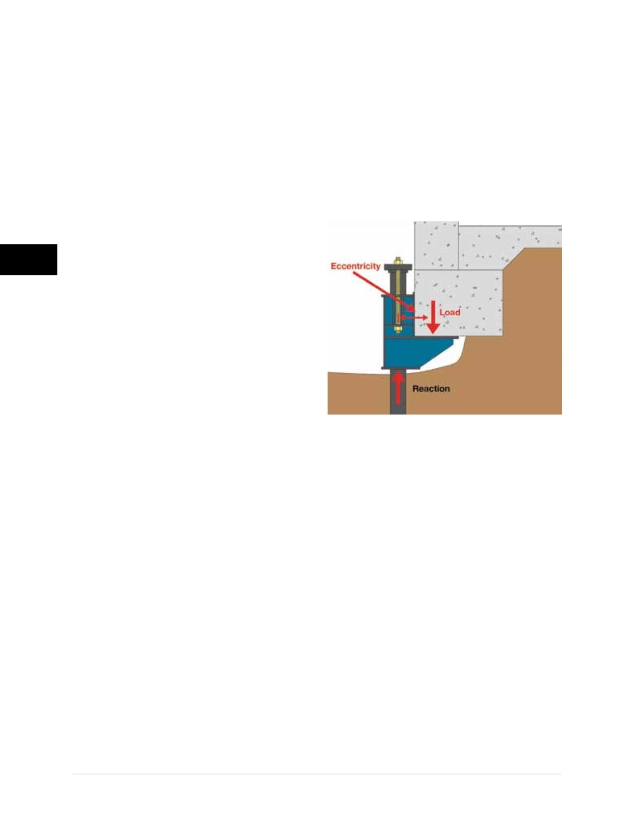
3.3.1.1 Eccentric Loading
Pier tubes of push pier systems utilizing under-
footing and flush-mount brackets are not
located directly under the structure’s footing.
Therefore, these systems are eccentrically
loaded and in turn need to resist the bending
forces generated by this loading condition
(Figure 3.3.1.1.a)
. The eccentricity generated by
under-footing and flush-mount bracket systems
is in reality shared by the pier and the structure.
In general, the more rigid the pier system and
its connection to the foundation, the more the
system acts as an extension of that foundation
and the more eccentricity must be absorbed by
the structure. This bending or twisting imparted
to the structure can be resisted by the internal
strength of the foundations and connections
to the superstructure, by passive resistance of
the soil along the opposite face of the footing
and/or foundation wall, by bracing with internal
structural elements such as floor slabs and
shear walls, and by support generated at
building corners. When the eccentricity cannot
be resisted by such conditions, the piers can
be staggered or paired on opposing sides of
the foundation. Multiple piers are often needed
at column locations simply to balance the load
and prevent tipping of the footing. Evaluation of
the eccentric loading condition on the structure
should be completed by a qualified design
professional on a case by case basis.
Figure 3.3.1.1.a
Eccentric loading
condition for under-footing bracket