


 227 / 365

© 2014 Foundation Supportworks
®
,
Inc.
All Rights Reserved
p 227
Chapter 3
Hydraulically-Driven Push Piers
CHAPTER 3
HYDRAULICALLY-DRIVEN PUSH PIERS
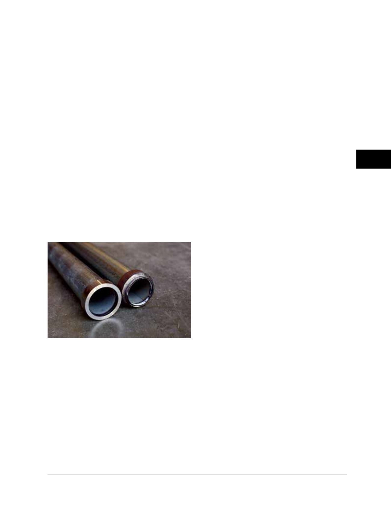
3.3.2.1 Friction Reduction Collar
A friction reduction collar is included at the
bearing end of push pier system starter tubes
(Figure 3.3.2.1.a)
. This collar consists of a 1-inch
long slice of a slightly larger round shaft section
slid over and welded to the end of the starter
tube, or a machined ring with a pressed fit.
These friction reduction collars have outside
diameters
1
-inch larger than their respective
pier sections and serve to either create annular
space or remold the soil around the pier shaft as
it is advanced through the soil. The reduction in
frictional resistance on the outside surface of the
pier results in a driven pier that generates most
of its capacity in end bearing. With reduced skin
friction and high bearing pressures generated
at the pier tip, push pier systems with friction
reduction collars also generally penetrate
deeper into the ground (than a frictional pier)
and advance through weak or marginal soils to
bear on competent material below.
It iscommontothinkofpushpiersasbeingadvanced
through overburden soils to bear on bedrock. This
may or may not be the case. For residential and
light commercial projects with light to moderate pier
loads, adequate resistance may be achieved within
very stiff to hard clay soils or medium dense to
dense sand and gravel. Allowable pier capacities of
15 to 20 kips, with a factor of safety of 1.5, may be
achieved in soils having standard penetration test
N-values around 30 blows per foot. Higher strength
soils or rock would therefore be required to develop
higher pier capacities.
The soils displaced or remolded by the friction
reduction collar “heal” back around and against the
shaft over time, generating an additional frictional
component to the pier’s capacity. This effect is
often referred to as pile “set up” when driving larger,
higher capacity pipe piles or H-piles. Set up can
occur within a matter of hours, days or weeks, and
is the reason piering contractors generally try to
start and finish installation of a push pier the same
day and, in some unique conditions, before a work
break is taken. Although this frictional capacity
can be significant, it is conservatively ignored in
most cases in the determination of the pier’s factor
of safety against settlement. The final drive force is
measured and documented prior to development
of the soils ultimate frictional resistance. Push pier
system factors of safety are further discussed in
Section 3.9.1.
3.3.3 Pier Tube
Pier tubes follow the starter tube during installation
and have a crimped or plug-welded slip-fit internal
coupling at the leading end (see next section). The
push pier tubes and couplings are manufactured
from hollow round structural steel sections.
Models PP237 and PP288 push pier tubes are
available in standard lengths of 18 and 36 inches.
The 18-inch long pier tubes are again used for
limited headroom or crawl space applications.
Models PP350 and PP400 pier tubes are available
in standard lengths of 36 inches only.
3.3.3.1 Coupling
Pier tube sections are coupled with an internal
slip-fit connection
(Figure 3.3.3.1.a)
. A hollow
round shaft section with an outside diameter
smaller than the inside diameter of the respective
pier tube is crimped (button-punched) or plug-
welded to the leading end. The internal coupler
extends one-half its length inside the pier
tube and one-half its length beyond the end
to maintain direct bearing of the pier sections.
The coupling is not pinned or bolted and is
therefore generally considered and utilized for
compression applications only.
Figure 3.3.2.1.a
PP288 starter tubes with pressed
fit and welded friction reduction collars