


 302 / 365

© 2014 Foundation Supportworks
®
,
Inc.
All Rights Reserved
p 302
Chapter 4
Miscellaneous Structural Support Products
CHAPTER 4
MISCELLANEOUS STRUCTURAL SUPPORT PRODUCTS
4.3 PowerBrace
™
System
4.3.1 Summary Description
The PowerBrace
™
System is designed
and manufactured by PowerBrace, LLC to
laterally support bowed, leaning and sheared
foundation walls. The system has been used
for over a decade with thousands of successful
installations throughout the United States
and Canada. The PowerBrace
™
System is a
patented system that, when installed properly,
will not only stabilize foundation walls against
further appreciable lateral movement, but
also in many cases will improve the wall’s
position over time. A steel beam is positioned
against the foundation wall and braced at the
top and bottom with brackets. The bottom
angle bracket is bolted to the concrete floor.
The adjustable top bracket is connected to
the joists supporting the floor system above
(See Figure 4.3.1.a)
. Technical specifications
and spacing guidelines for the PowerBrace
™
System can be found in Appenix 4B.
4.3.2 Installation Steps
The following steps provide a broad overview for
a typical PowerBrace
™
installation. Intermediate
steps, installation equipment and tools used,
considerations for obstructions along the wall,
and considerations for variable joist details
are not addressed. It is critical that adequate
blocking be installed along and between floor
joists supporting the first floor so loads are
adequately and effectively transferred into
the floor system without damage. Contact
PowerBrace, LLCat (800) 556-5697with technical
questions and for a copy of the manufacturer’s
installation guidelines.
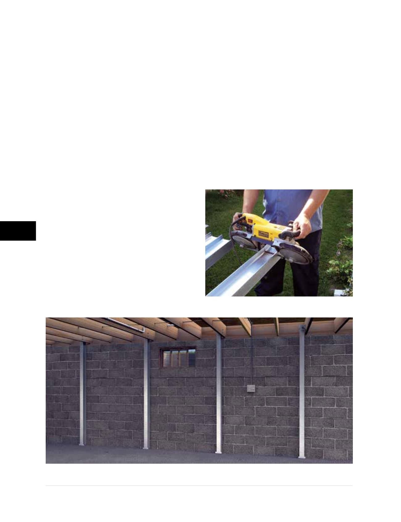
Step 1
– Measure from the top of the basement
slab to 1 inch from the underside of the first
floor. Cut the PowerBrace
™
beam to this length
(Figure 4.3.2.a1)
.
Figure 4.3.2.a1
Rendering of PowerBrace
™
installation
Figure 4.3.2.a1