


 303 / 365

© 2014 Foundation Supportworks
®
,
Inc.
All Rights Reserved
p 303
Chapter 4
Miscellaneous Structural Support Products
CHAPTER 4
MISCELLANEOUS STRUCTURAL SUPPORT PRODUCTS
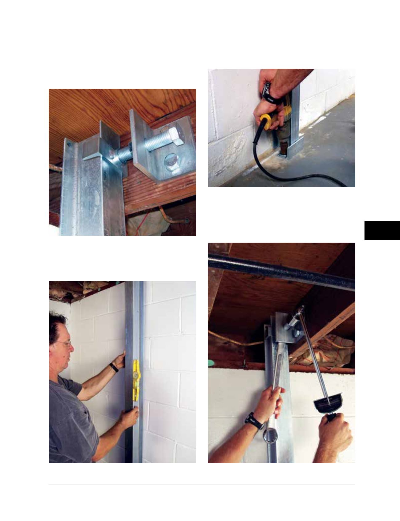
Step 2
– The top bracket is attached to the floor
joist and the top of the beam is positioned within
the bracket
(Figure 4.3.2.a2)
. Install blocking
along and within floor joists in accordance with
the manufacturer’s installation guidelines.
Step 3
– PowerBrace
™
beam is plumbed
(Figure 4.3.2.a3)
.
Step 4
– The bottom bracket is positioned at
the bottom of the beam and anchored to the
concrete floor
(Figure 4.3.2.a4)
.
Step 5
– The PowerBrace™ System can be
tightened over time for possiblewall improvement
(Figure 4.3.2.a5)
.
Figure 4.3.2.a2
Figure 4.3.2.a3
Figure 4.3.2.a4
Figure 4.3.2.a5