


 34 / 365

© 2014 Foundation Supportworks
®
,
Inc.
All Rights Reserved
p 34
Chapter 2
Helical Foundation Systems
CHAPTER 2
HELICAL FOUNDATION SYSTEMS
• There is no need to embed structural elements
below the proposed ground surface elevation
on the low side of the soil nail wall. Soldier
pile and sheet-pile walls require minimum
embedment depths for wall stability.
• Soil nail wall construction is typically quicker
than other earth retention methods.
• Soil nail walls can be constructed in remote
areas with smaller equipment.
• Soil nail walls have performed well during
seismic loading events due to the overall
system flexibility.
A helical soil nail typically consists of square shaft
lead and extension sections with small diameter
(6 to 8 inches) helix plates spaced evenly
along the entire shaft length
(Figures 2.9.a1
and
2.9.a2)
. The helical soil nail is installed by
application of torque, similar to the installation of
a helical tieback. The helical soil nail is a passive
bearing element, which relies on movement
of the soil mass and active earth pressures to
mobilize the soil shear strength along the nail. In
contrast, a tieback is pre-tensioned to mobilize
the soil shear strength around the helix plates.
Excavation, soil nail installation and application
of wall facing is completed in steps from the top
of the wall downward.
2.9.1 Construction
Methodology
Soil nail walls are constructed from the top
down where the excavation proceeds as shown
in
Figure 2.9.1.a
. The construction sequence for
a typical helical soil nail wall includes:
• Initial excavation about 3 to 5 feet deep
depending upon design parameters and
soil conditions
• Installation of the first row of helical soil nails
to the required inclination angle, torque and
embedment length
• Placement of drainage medium (if required)
• Placement of wall reinforcement and bearing
plates
• Placement of shotcrete to the required design
wall thickness
• After shotcrete has cured, repeat sequence
for successive rows of soil nails. Continue
process to the final design depth (wall height).
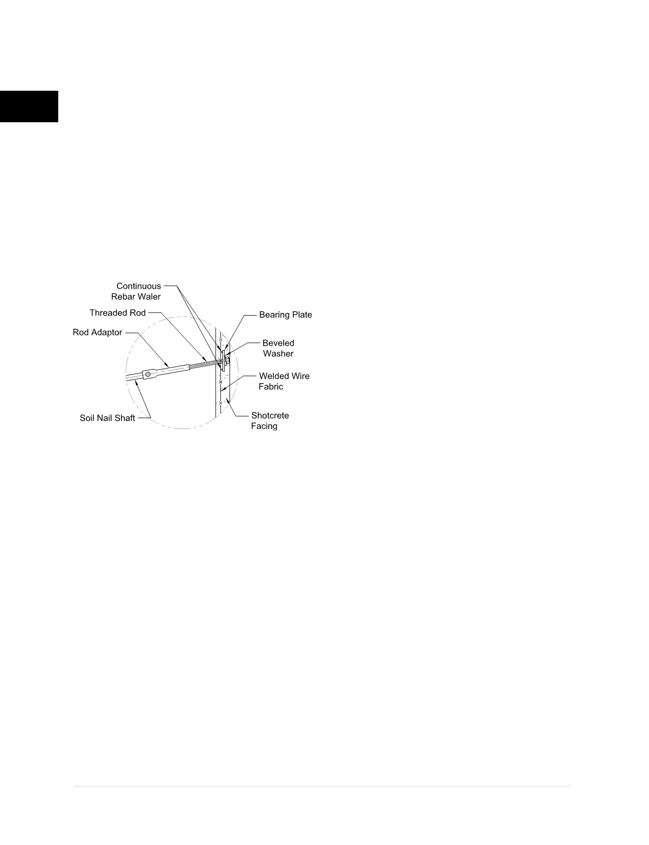
Figure 2.9.a2
Nail head to wall detail