


 32 / 365

© 2014 Foundation Supportworks
®
,
Inc.
All Rights Reserved
p 32
Chapter 2
Helical Foundation Systems
CHAPTER 2
HELICAL FOUNDATION SYSTEMS
walls, for example, are generally designed with
significant reinforcing steel on the backfilled
side of the wall where tension and bending
are greatest. Reinforcing steel within the
compression side of the wall is generally the
minimum required by code. Tieback installation
induces a negative bending in the cantilevered
wall for which the wall was not originally
designed. Walls to be stabilized with tiebacks, or
walls that will be designed with tieback support,
should be reviewed by a design professional.
The assumed failure plane behind an earth
retaining wall is dependent upon soil conditions
and wall type. As a general rule of thumb, a failure
plane can be projected from the bottom back face
of the wall upward at an angle of 45-
Φ
/2 (degrees)
from vertical for both active and at-rest conditions.
For retaining walls and basement walls, this failure
plane is usually assumed to begin at the bottom
of wall. For sheet pile walls, the failure plane is
usually assumed to begin at the mud line.
Failure modes for restrained walls should be
evaluated for internal stability, external stability,
bearing capacity and global stability. It is the
responsibility of the design professional of record
to perform these evaluations. Typical factors of
safety for helical tiebacks used in conjunction
with earth retention systems are generally on
the order of 1.3 to 1.5 for temporary applications
and 2.0 for permanent applications.
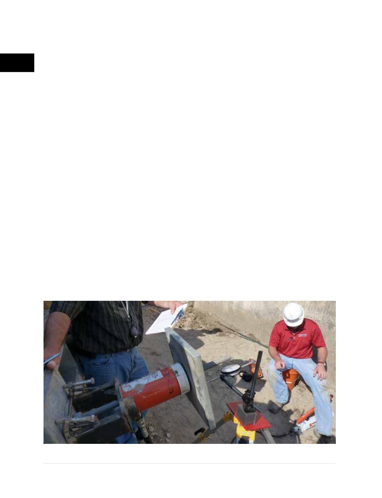
Foundation Supportworks recommends that
all helical anchors and tiebacks (excluding
soil nails) be pre-tensioned or proof-tested
following installation (Figure 2.8.1.c).
Pre-tensioning to 1.0 to 1.33 times the design
working load minimizes deflection of the
tiebacks and structure as the tiebacks are put
into service and the soil strength around the
helix plates is mobilized. Tiebacks installed
to support existing walls are typically locked
off at 0.75 to 1.1 times the design working
load after proof-testing. Helical anchors
and tiebacks to be cast into new concrete
retaining walls may be completely unloaded,
or locked off with a modest seating load, after
proof-testing. Tiebacks can be “pull tested”
or load tested to typically two (2) times the
design working load or more to identify the
ultimate system capacity, better assess soil
conditions and soil/anchor interaction, and
validate design assumptions and parameters.
Tiebacks that undergo load testing to
greater than 1.5 times the design working
load, or failure, are generally considered
sacrificial and should not be used as
production tiebacks.
Figure 2.8.1.c
Pre-tensioning helical tieback