


 30 / 365

© 2014 Foundation Supportworks
®
,
Inc.
All Rights Reserved
p 30
Chapter 2
Helical Foundation Systems
CHAPTER 2
HELICAL FOUNDATION SYSTEMS
that are cracked, leaning and/or bowing
(Figures
2.8.c1 and 2.8.c2)
. The wall distress may be a
result of changes in soil moisture conditions,
rise in groundwater levels, plugging of the wall
drainage system over time, plumbing leaks,
expansive clay soils, frost-jacking, or surcharge
loads above the wall.
2.8.1 Design Considerations
The helix plates along the tieback shaft must be
located beyond the active wedge or failure plane
to provide proper anchorage. The last helix plate
from the tip (closest to the wall) shall be at least
five (5) times its diameter beyond the failure
plane
(Figure 2.8.1.a)
. The helix plates should
also be located at least five (5) diameters below
the ground surface of the retained soils to model
deep foundation behavior. Multiple tiebacks
shall have a center to center spacing at the
helices of at least three (3) times the diameter of
the largest helix plate to avoid significant stress
overlap within the bearing soils.
Helical tiebacks are often installed at a
downward angle from horizontal, typically on the
order of 5 to 15 degrees. This downward angle is
often considered in order achieve the 5D depth
criteria below the surface of the retained soils,
to increase the vertical effective overburden
stress at the helix depths (in granular soils), or
to extend the helix plates to a deeper, more
competent soil layer. A slight downward angle
may also be considered to simply minimize the
potential for groundwater to follow the shaft and
seep through the wall penetration.
Tiebacks designed with a downward angle
should be installed to a capacity higher than the
calculated/required horizontal tieback capacity
(Figure 2.8.1.b)
. The calculated horizontal
tieback capacity (T
CH
) is determined from
analysis considering the various loads on the
wall. If the tieback is designed for an installation
angle, alpha (
α
), then the tieback should be
installed to a capacity T
R
and its corresponding
value of torque if the torque correlation method
is used for capacity verification.
Remember
that the torque-correlated ultimate capacity
should exceed the design working load by an
appropriate factor of safety.
T
R
= T
CH
/ cosα
The vertical component of the tieback force
should also be considered so as not to overstress
the wall or the wall bearing soils. The vertical
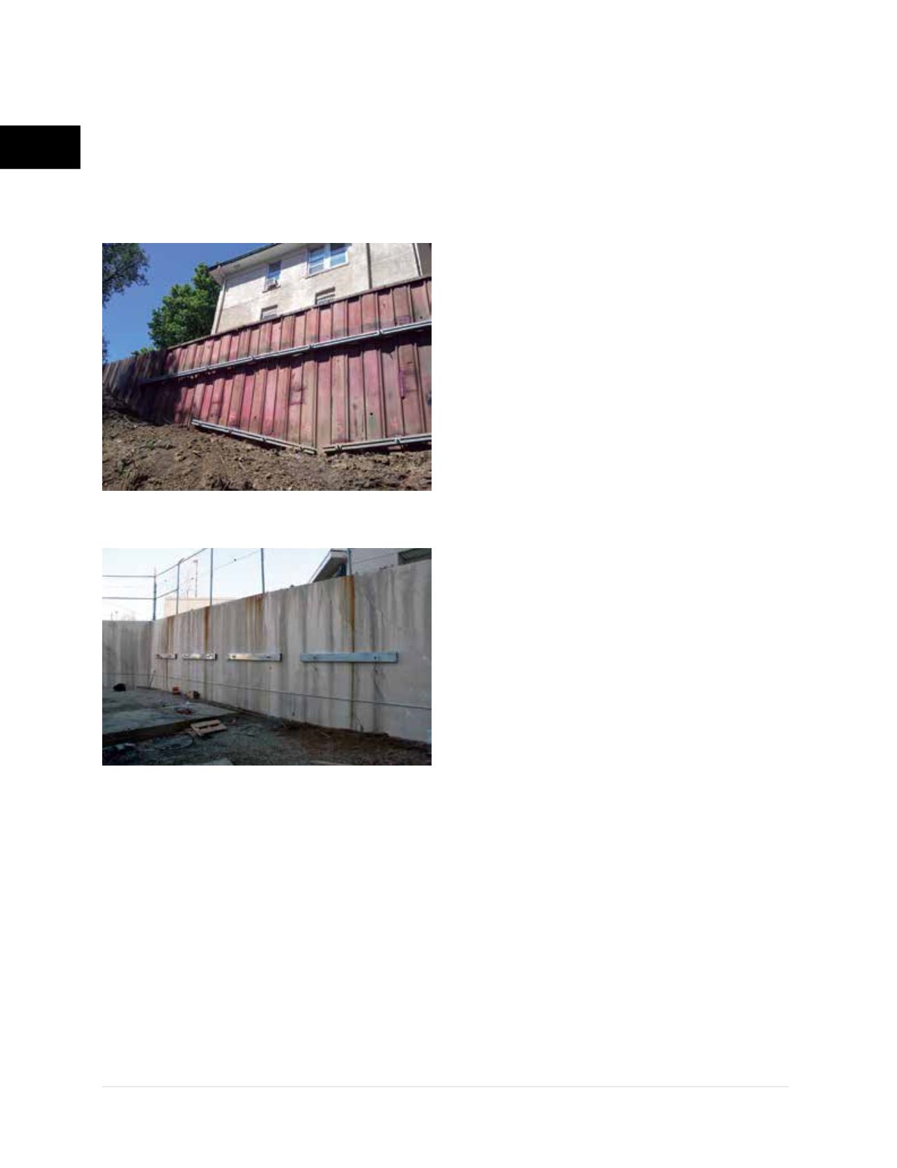
Figure 2.8.c2
Helical tiebacks and tube steel
walers stabilize concrete retaining wall
Figure 2.8.c1
Helical tiebacks stabilize
sheet pile wall below historic home