


 48 / 365

© 2014 Foundation Supportworks
®
,
Inc.
All Rights Reserved
p 48
Chapter 2
Helical Foundation Systems
CHAPTER 2
HELICAL FOUNDATION SYSTEMS
The followingmachine specifications are required:
• The machine should have a bi-directional
auxiliary circuit to power the drive head.
• Hydraulic fluid pressure output from the circuit
used to power the drive head should meet the
drive head specifications. On some machines,
it may be necessary to adjust the relief valve
on the machine’s auxiliary system hydraulic
pump to provide the appropriate pressure
specified by the drive head manufacturer.
• The flow rate of hydraulic fluid to the drive head
should meet the drive head specifications for
optimum performance during installation.
• The machine should have adequate weight to
resist torsional forces from the drive head and
to allow for proper crowd during installation.
FSI offers portable hand-held equipment for
operating smaller, lighter-weight drive heads
when access with machinery is not feasible.
The drive heads can be powered by auxiliary
hydraulic circuits of machinery or by portable
hydraulic power packs. The power source
should meet the operating specifications of the
drive head. A portable, remote valve assembly
allows for safe operation of the drive head when
used with the hand-held equipment.
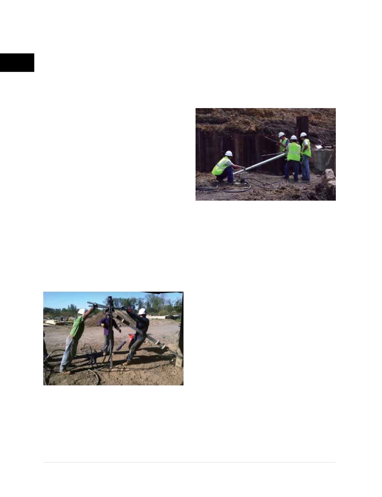
The drive head is mounted to the frame of the
hand-held equipment
(Figure 2.12.2.1.e)
so that it
can be supported and operated by at least two
technicians. To provide the reaction for the output
torque, a telescoping torque arm is attached to the
frame of the hand-held equipment. The torque arm
(Figure 2.12.2.1.f)
is secured against the ground, a
wall or other suitable structure or device capable
of resisting the torsional forces transferred to
the end of the torque arm by the drive head.
Hand-held equipment is typically limited to a
maximum installation torque of 6,000 ft-lb, or less.
Consult FSI with any questions regarding the rated
capacities of FSI hand-held equipment.
Installers and personnel in the immediate
work area should be properly trained in
the safe operation and use of hand-held
equipment. The torque arm shall be properly
restrained for the direction of arm rotation.
Reversing the rotation also requires
restraining of the torque arm in the opposite
direction. Personnel in the work area
should understand the direction that the
torque arm will tend to swing and position
themselves in a safe location (considering
any possibility that the torque arm could
break free from its restraint). Appropriate
installation geometry should be maintained
during pile installation. The ideal position for
the torque arm is as follows:
1) Arm is fully extended and is restrained at
its maximum radius from the pile shaft.
2) Arm is at an angle which is perpendicular
to the pile shaft.
Actual installation geometry is adjustable
and will vary, but in no circumstance shall the
torque arm be placed at an angle in excess
of 35 degrees from perpendicular and in no
circumstance shall the torque arm restraint
Figure 2.12.2.1.e
Hand-held equipment
Figure 2.12.2.1.f
Torque arm