


 233 / 365

© 2014 Foundation Supportworks
®
,
Inc.
All Rights Reserved
p 233
Chapter 3
Hydraulically-Driven Push Piers
CHAPTER 3
HYDRAULICALLY-DRIVEN PUSH PIERS
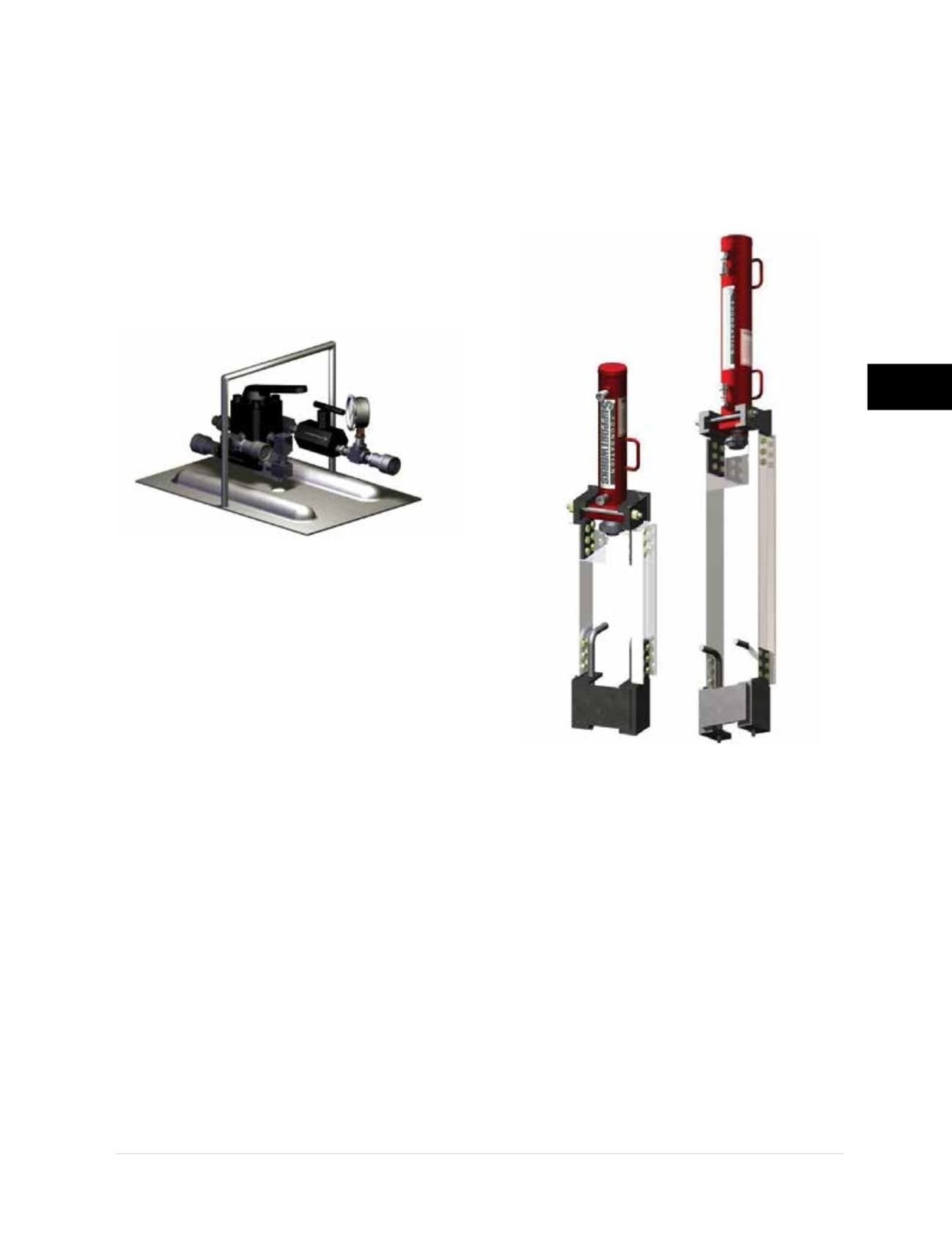
3.8.3 Remote Valve Assembly
The remote valve assembly is used to control the
hydraulic fluid pressure from a gasoline pump to
the drive cylinder during foundation pier and slab
pier installation. The remote valve assembly is
typically placed near the bracket and drive stand
assembly to provide greater control and response
during the driving operation. The FSI remote valve
assembly is shown in
Figure 3.8.3.a
. The remote
valve assembly is not used with an electric pump.
3.8.4 Hoses and Fittings
Hoses and fittings should be designed for the
maximum system pressure. Hose lengths of 10,
50 and 100 feet are available to accommodate
either sequential connection of lift cylinder
assemblies or connection through a manifold
system. FSI offers both flush face and threaded
fittings for the cylinder and pump connections.
3.8.5 Drive Stands
Drive stands provide the means for advancing
pier tubes through foundation and slab
brackets. The drive stand is positioned over
and then secured to the bracket. Hydraulic drive
cylinders or rams are then set within the top
fixture of the drive stands. Lengths of the drive
stand legs have been specifically designed for
the FSI standard pier tube lengths of 36 inches.
The drive stand used for PP288 installation
within a crawl space has shorter legs designed
for 18-inch long pier sections. There are several
drive stand assembly options available for the
multiple pier sizes and bracket details.
Figure
3.8.5.a
shows crawl space and standard drive
stand assemblies for the PP288 system. The
FSI drive stand assembly specifications, along
with general dimensioning, are included in
Appendix 3B.
3.8.6 Lift Cylinder Assemblies
Lift cylinder assemblies are connected to the
thread rod or coil rod of the bracket assembly
after the pier cap has been placed. Refer back
to
Figure 3.8.1.b
. The lift cylinder assemblies
provide the final application of force to first
stabilize and then lift the structure. After the
stabilization or lift force has been applied, the
top nuts on the thread or coil rods of the bracket
assembly are tightened down to the pier cap,
thereby locking off the load. See Appendix 3C
for lift assembly specifications.
Figure 3.8.3.a
Remote valve assembly
Figure 3.8.5.a
Crawl space and standard drive stand
assemblies for the PP288 push pier system