
© 2014 Foundation Supportworks
®
,
Inc.
All Rights Reserved
p 231
Chapter 3
Hydraulically-Driven Push Piers
CHAPTER 3
HYDRAULICALLY-DRIVEN PUSH PIERS
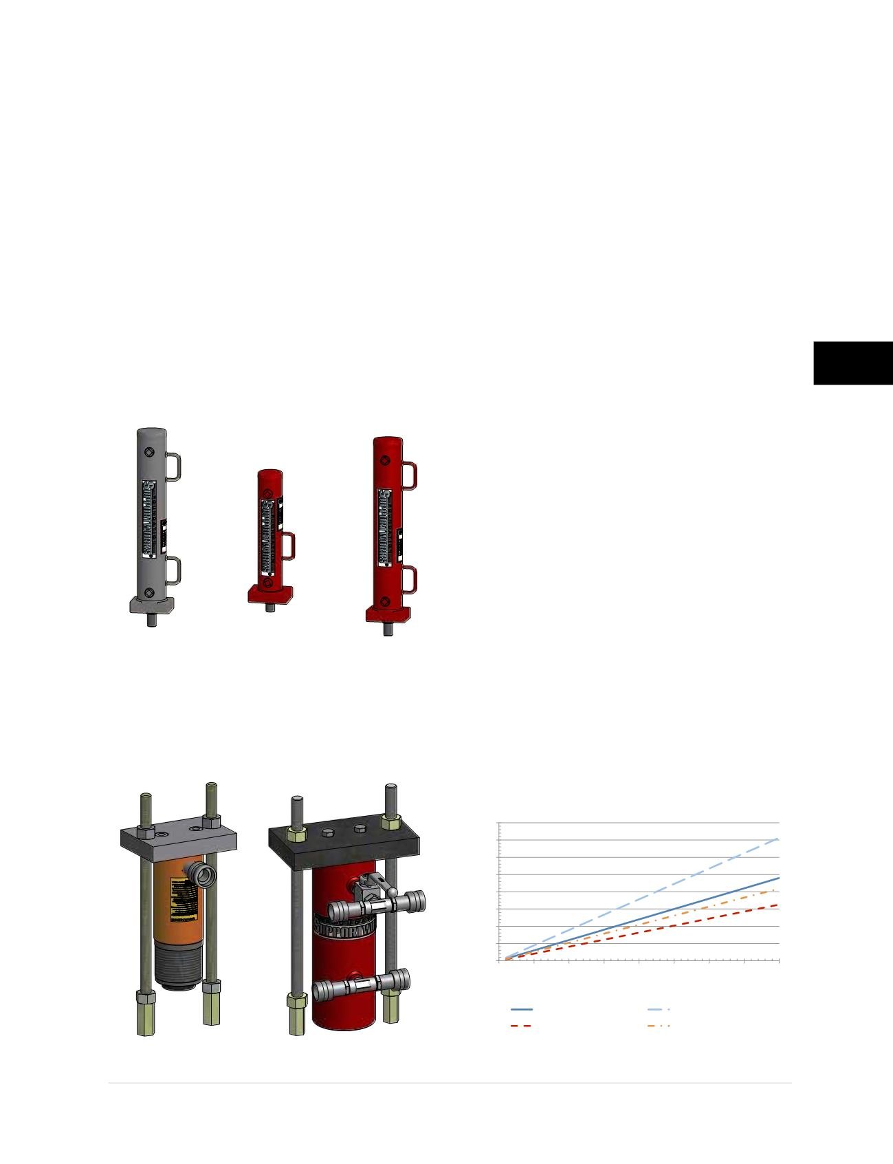
3.8.1 Drive and Lift Cylinders
Hydraulic drive cylinders (also commonly referred
to as “rams”) are used to push (drive) pier sections
below the existing footing until the target ultimate
pressure or load is achieved or until the structure
begins to mobilize (lift response). Hydraulic lift
cylinders are then used at each of the multiple
pier locations to provide the final lock-off load for
stabilization or to lift the structure, if required. FSI
offers three drive cylinder (FS425DC, FS35CSDC
and FS35DC) and two lift cylinder (FS256LC and
FS35LC) options. The FS35CSDC drive cylinder
is a shorter version of FS35DC for use in limited
headroom and crawl space applications. The FSI
drive and lift cylinders are shown in
Figures 3.8.1.a
and 3.8.1.b
. Drive and lift cylinder specifications
are provided in Appendix 3B (Drive Stand
Specifications) and Appendix 3C (Lift Assembly
Specifications), respectively.
3.8.2 Hydraulic Pumps
Hydraulic pumps used to drive pier tube
can be electric or gasoline powered. The
selection of the pump unit should take into
consideration the maximum drive pressure
(ultimate pier capacity) required and the rate
of pier installation desired. The flow rate of the
hydraulic pump will affect how fast piers can be
advanced with higher flow units allowing faster
pier installation. That said, gasoline pumps
generally provide greater flow than electric
pumps and are therefore preferred for deep
foundation pier installation. Electric pumps
are often recommended for the stabilization/
lift operation of foundation pier installation
and for both the driving and stabilization/lift
operations of slab pier installation. With lower
flow rates, electric pumps install piers slower
and provide greater control to reduce potential
overstressing of the concrete slab or footing
should sudden spikes in pressure/load occur.
FSI offers two models of electric pumps and
two models of gas pumps.
The effective area of the hydraulic drive cylinder
used will also have an effect on installation speed.
FSI drive cylinders FS35DC and FS35CSDC have
an effective area of 9.62 in
2
while operating in
extension mode and 6.48 in
2
while operating in
retraction mode. FSI drive cylinder FS425DC has
effective areas of 14.18 in
2
and 11.04 in
2
for the
extension and retraction modes, respectively.
With different effective areas, the drive cylinders
will have different extension and retraction rates
Figure 3.8.1.b
FSI lift cylinder assemblies. Left to
Right; FS238LCA (with FS256LC) and FS35LCA.
0
20
40
60
80
100
120
140
160
0.0
0.5
1.0
1.5
2.0
2.5
3.0
3.5
4.0
Extend or Retract Rate (inches/min)
Flow Rate (gpm)
FS35DC/FS35CSDC - Extended
FS35DC/FS35CSDC - Retract
FS425DC - Extended
FS425DC - Retract
Figure 3.8.2.a
FSI drive cylinder
extend and retract rates
Figure 3.8.1.a
FSI drive cylinders. Left to Right;
FS425DC, FS35CSDC and FS35DC (no relative scale).


