


 24 / 365

© 2014 Foundation Supportworks
®
,
Inc.
All Rights Reserved
p 24
Chapter 2
Helical Foundation Systems
CHAPTER 2
HELICAL FOUNDATION SYSTEMS
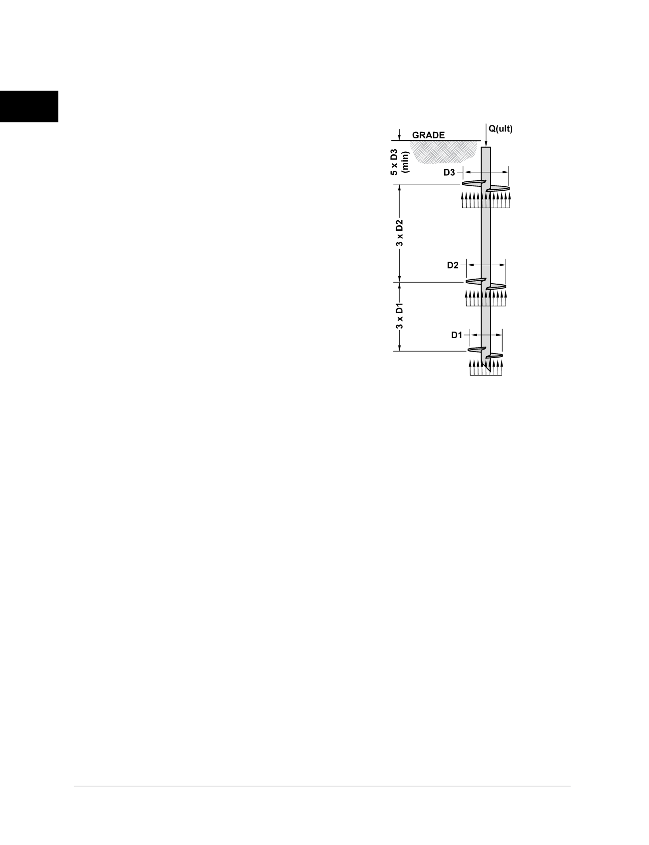
2.7.1 Individual Bearing Method
The individual bearing method (Adams and Klym
1972; Hoyt and Clemence 1989) states that the
ultimate pile capacity is equal to the sum of the
individual helix plate capacities. Spacing of the
helix plates along the shaft is generally 3 times
the diameter of the leading plate, the uppermost
helix plate is embedded to a depth of at least
5 diameters, and skin friction along the shaft is
generally ignored for shaft sizes less than 6 inches
in outside diameter.
Figure 2.7.1.a
illustrates the
load transfer mechanism for the individual bearing
method in compression loading.
Helical pile capacity by the individual bearing
method can be calculated from:
Q
u
= ∑A
h
(cN
c
+ q’N
q
+ 0.5γBN
γ
)
Where,
Q
u
= Ultimate Pile Capacity (lb)
c
= Cohesion at Helix Depth (lb/ft
2
)
q’
= Effective Vertical Overburden
Stress at Helix Depth (lb/ft
2
)
γ
= Soil Unit Weight (lb/ft
3
)
B
= Diameter of Helix Plate (ft)
A
h
= Area of Helix Plate (ft
2
)
N
c
, N
q
, N
γ
= Dimensionless Bearing Capacity
Factors
The last part of the equation that includes the helix
diameter (B) is often ignored in the calculation of
end-bearing capacity of deep foundations. The
diameter or width of the pile is relatively small and
therefore this portion of the equation contributes
little to the overall pile capacity. With that portion
of the equation conservatively ignored, the
equation further simplifies to:
Q
u
= ∑A
h
(cN
c
+ q’N
q
)
For purely cohesive soils
with
Φ
= 0 and c = s
u
(soil undrained shear strength), N
c
≈ 9 and N
q
=
1. The equation can conservatively be rewritten
again as:
Q
u
= ∑A
h
(9c)
For purely granular (frictional) soils
with c = 0,
the equation can be rewritten as:
Q
u
= ∑A
h
(q’N
q
)
Bearing capacity factors N
c
and N
q
are typically
provided in foundation design textbooks and these
values may not be appropriate for use in helical
pile design. Research has shown that N
q
may not
only be a function of the soil friction angle, but also
pile embedment depth, pile type and installation
method (drilled, driven, etc.). Unfortunately, there
has been little research to investigate how N
q
might
vary for helical piles. Since helical piles are generally
considered low-displacement to displacement piles
due to the helix plates and shaft, one could theorize
similar N
q
values as determined by Meyerhof
(1976) for driven piles, with a reduction to account
for soil disturbance created by the helix plates.
Foundation Supportworks recommends N
c
and N
q
bearing capacity factors calculated by the following
equations and shown graphically in
Figure 2.7.1.b
:
N
c
= (N
q
– 1)cotΦ ≥ 9
N
q
= 1 + 0.56(12Φ)
Φ/54
These values of N
c
and N
q
are slightly lower and
therefore more conservative than the values
typically provided in textbooks.
Figure 2.7.1.a
Individual Bearing Method