


 20 / 365

© 2014 Foundation Supportworks
®
,
Inc.
All Rights Reserved
p 20
Chapter 2
Helical Foundation Systems
CHAPTER 2
HELICAL FOUNDATION SYSTEMS
2.6 Design Considerations
2.6.1 Spacing and Depth
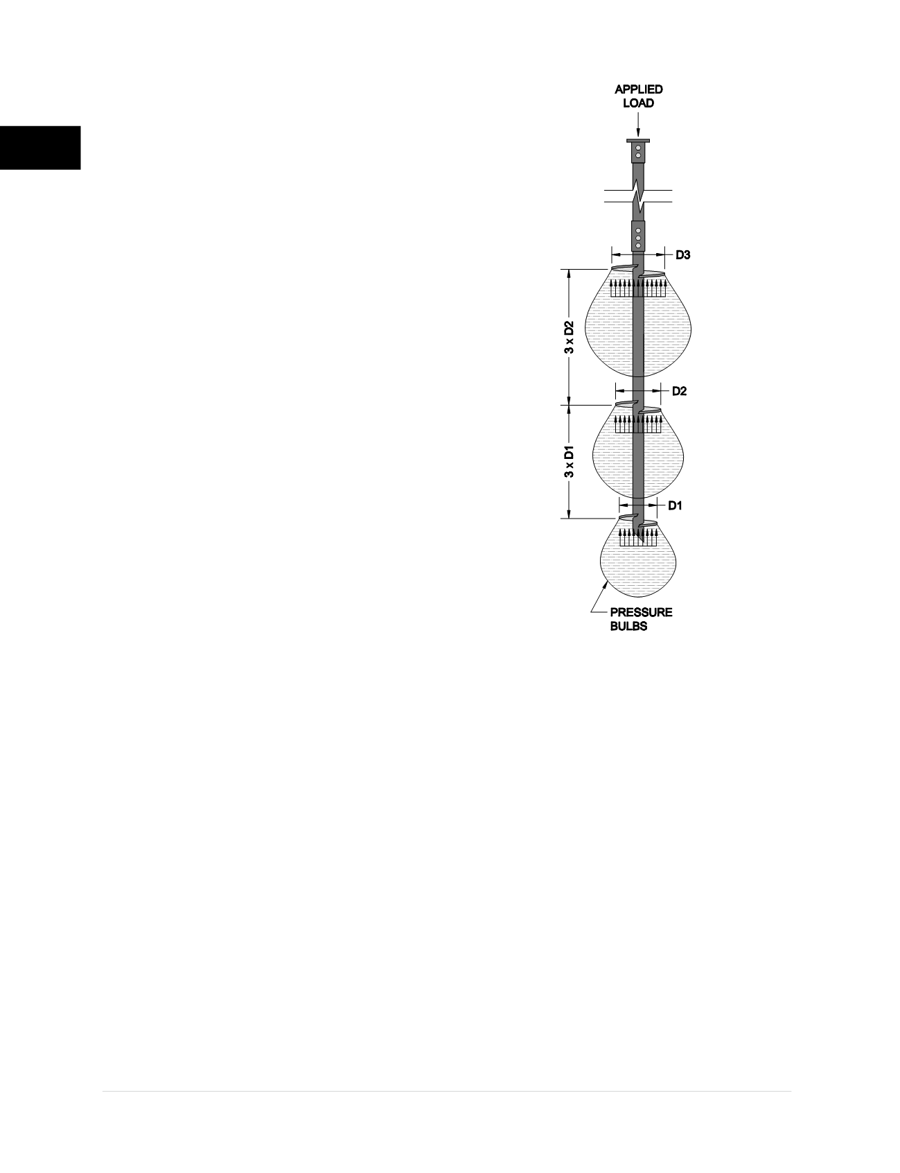
Helical piles are designed such that most
of the axial capacity of the pile is generated
through bearing of the helix plates against
the soil. The helix plates are typically spaced
three diameters apart along the pile shaft to
prevent one plate from contributing significant
stress to the bearing soil of the adjacent plate.
Significant stress influence is limited to a “bulb”
of soil within about two helix diameters from the
bearing surface in the axial direction and one
helix diameter from the center of the pile shaft
in the lateral direction. Each helix plate therefore
acts independently in bearing along the pile
shaft
(Figure 2.6.1.a)
. Helical piles designed with
helix plate spacing in accordance with AC358
could therefore use either the Individual Bearing
or Cylindrical Shear Methods of calculating
capacity. Helical piles manufactured with more
closely-spaced helix plates should consider the
Cylindrical Shear Method only. These design
methods are presented in Section 2.7.
Axially loaded helical piles shall have a center
to center spacing at the helix depth of at least
three (3) times the diameter of the largest helix
plate to avoid group efficiency effects (ICC-ES
AC358). The tops of the piles may be closer at
the ground surface, but the piles be installed at
a batter away from each other in order to meet
the spacing criteria at the helix depth.
The center to center spacing of laterally loaded
piles shall be at least eight (8) times the diameter
of the pile shaft at the ground surface and four
(4) times the diameter of the largest helix plate
measured at the plate depths (ICC-ES AC358).
If both of these criteria are not met, an analysis
should be completed to determine if there should
be a reduction in the lateral capacity per pile.
For tension applications, the uppermost helix
plate shall be installed to a depth at least twelve
(12) diameters below the ground surface (ICC-
ES AC358). Default torque correlation factors
(capacity to torque ratios) have been verified
for conforming systems tested and evaluated in
tension applications at and below these depths.
Design professionals may still determine that
shallower installations are appropriate for the
project given the site-specific soil conditions.
The uppermost helix plate shall be embedded in
the ground to a depth of at least five (5) diameters
to create a deep foundation bearing condition.
The upper helix plate shall also be located
below the depth of seasonal frost penetration
and below the “active zone”; i.e., the depth of
soil that undergoes seasonal volume changes
with changes in moisture content. The depth of
the uppermost helix plate would therefore be
determined from the greatest of these values.
Figure 2.6.1.a
Helix plate spacing with
bulbs of significant stress influence