


 19 / 365

© 2014 Foundation Supportworks
®
,
Inc.
All Rights Reserved
p 19
Chapter 2
Helical Foundation Systems
CHAPTER 2
HELICAL FOUNDATION SYSTEMS
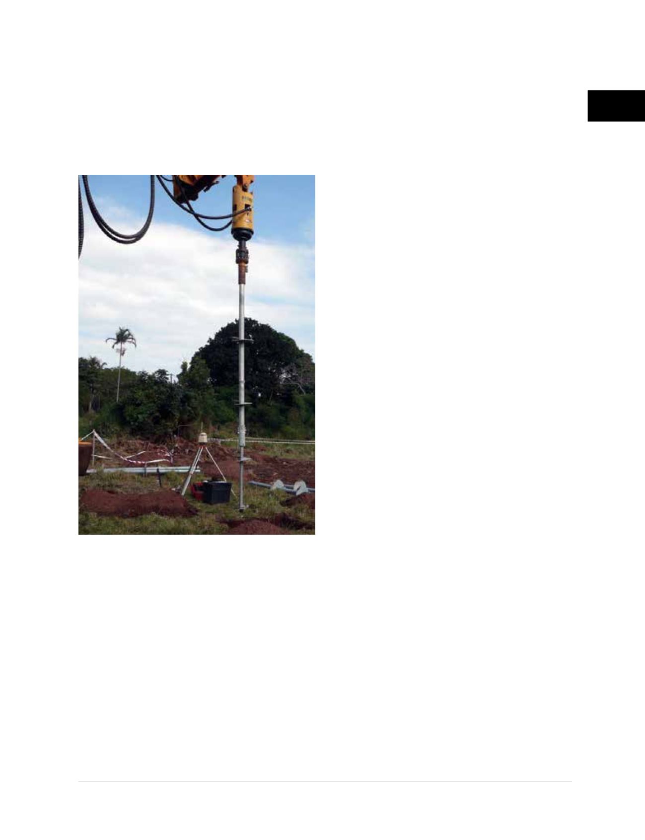
may also be considered to pass through or
penetrate into dense soil
(Figure 2.5.a)
. Where
large obstructions are encountered, the helical
piles may have to be offset from plan locations.
The project engineer should first be notified to
determine if other piles should be relocated or
if additional piles will be required.
• Helical piles will not typically penetrate hard
rock, defined by auger refusal by the drill
rig or Standard Penetration Test (SPT) blow
count values ≥ 50 blows/6 inches of sampler
penetration (ASTM D1586). Helical piles may
penetrate into hard clay, dense sand and soft or
weathered bedrock; however, larger installation
equipment is generally recommended to
provide “crowd” or axial force on the pile during
advancement into these soils. A square bar
stinger lead section may again be considered
along with the larger installation equipment.
• The slenderness of helical piles and their limited
exposed area to the surrounding soil does not
allow for generation of high lateral capacities.
In competent soils, allowable lateral capacities
may range from less than 1 kip to more than
5 kips for 2.875-inch to 3.5-inch O.D. round
shafts. Higher capacities may be achieved
as the central shaft size of the pile increases.
These capacities are typically achieved with
lateral deflections of one inch or more. Where
higher lateral loads are anticipated, or lower
deflection criteria required, lateral loads could
be resisted by (1) extending the structural
concrete grade beams or pile caps deeper to
take advantage of the passive resistance of
the soil, (2) incorporating battered helical piles
into the foundation design, (3) using structural
elements in the current design, such as floor
slabs with hairpin bars, or (4) incorporating
other structural elements to create fully-braced
conditions. Site-specific lateral load tests can
be completed to document the lateral capacity
to deflection relationship prior to installing
production piles.
Figure 2.5.a
Combination pile with HA175 stinger
coupled immediately to 3.5” O.D. shaft