


 50 / 365

© 2014 Foundation Supportworks
®
,
Inc.
All Rights Reserved
p 50
Chapter 2
Helical Foundation Systems
CHAPTER 2
HELICAL FOUNDATION SYSTEMS
2.12.2.3 Monitoring Torque
Monitoring torque is a key process during the
installation of helical piles since the installation
torque directly correlates to pile capacity in
accordance with the torque correlation method
described in Section 2.7.3. A number of devices
are available to assist in determining torque and,
ultimately, the calculation of pile capacity. These
devices range from simple pressure gauges
to shear pin indicators to more sophisticated
electronic data acquisition systems.
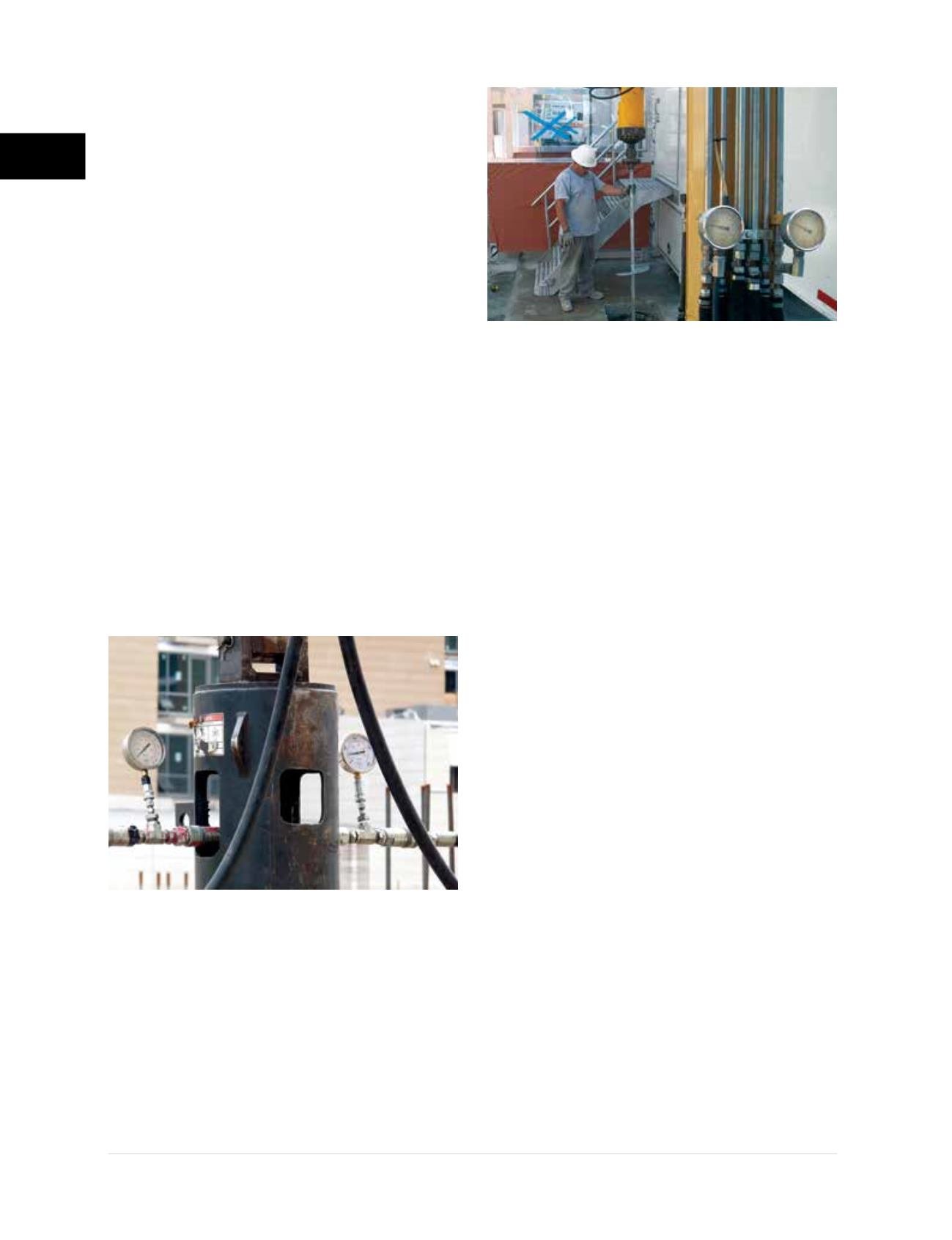
Dual hydraulic pressure gauges
(Figures
2.12.2.3.a1 and 2.12.2.3.a2)
can be used to
measure the “pressure drop” across a hydraulic
torque motor. This method is based on the
principle that the work output of the torque
motor is directly related to measurement of
the pressure drop across the motor as force
is applied. To measure the pressure drop, one
gauge is placed in line with the feed from the
hydraulic pump or machine to the drive head.
A second gauge is placed in line with the
return from the drive head back to the pump.
The return line pressure is subtracted from the
feed line pressure resulting in the determination
of “differential” pressure. The installation
torque can be calculated relative to the
differential pressure by applying the gear motor
multiplier (GMM) provided by the drive head
manufacturer. Most drive head manufacturers
provide correlation charts for quick conversion
of differential pressure to torque.
The return line gauge is an indicator of the
hydraulic system “back pressure”, which is
variable with each machine and may average
from 50 psi to over 800 psi. Systems with high
return line pressures may damage a hydraulic
torque motor. The installation of a “case drain” on
the hydraulic torque motor can prevent damage
to the motor seal. A case drain line is simply
directed back to the hydraulic fluid reservoir.
Some operators choose to use a single gauge
on the feed line side only, rather than to use a
second gauge to measure back pressure. This
can result in decreased accuracy and over-
estimation of applied torque if back pressure is
under-estimated or ignored all together.
Differential pressure cylinders
such as the
DP-1, are hydraulic cylinders with opposing
pistons within the cylinder body that measure
the differential pressure on a single gauge.
Similar to the use of dual pressure gauges, the
determination of torque is based on the pressure
drop across the motor and, subsequently, the
differential pressure to torque correlation.
Differential pressure gauge
technology
is based on similar principals as the DP-1.
Differential pressure gauges still measure the
feed and return line pressures to determine the
pressure drop across the motor, but with ports
for the lines within a single-gauge body. This
differential pressure, as in the case of the Tru
Torque model
(Figure 2.12.2.3.b)
, is related to
torque by the GMM for a specific drive head. The
Figure 2.12.2.3.a1
Dual pressure gauges
Figure 2.12.2.3.a2
Monitoring pressure gauges
while installing square shaft helical anchor