


 49 / 365

© 2014 Foundation Supportworks
®
,
Inc.
All Rights Reserved
p 49
Chapter 2
Helical Foundation Systems
CHAPTER 2
HELICAL FOUNDATION SYSTEMS
be placed at a distance less than 7 feet from
the axis of the pile shaft. The capacity of the
hand-held equipment decreases significantly
when used outside of these parameters. The
force that will be required to restrain the
torque arm will also vary, but even within the
operation parameters just described, restraint
forces can approach 1,000 lb. The torque arm
restraint is therefore recommended to be
capable of resisting a force of at least 1,500 lb.
Lateral restraint is not only required at the end
of the torque arm. The drive head shall also be
restrained from lateral movement.
Drive heads used with hand-held installation
equipment should not be operated at speeds
exceeding 10 rpm. Operators shall be ready
at the controls and prepared to shut down
the equipment at any moment.
Failure to properly restrain and operate the
hand held installation equipment per these
guidelines can result in serious injury or death.
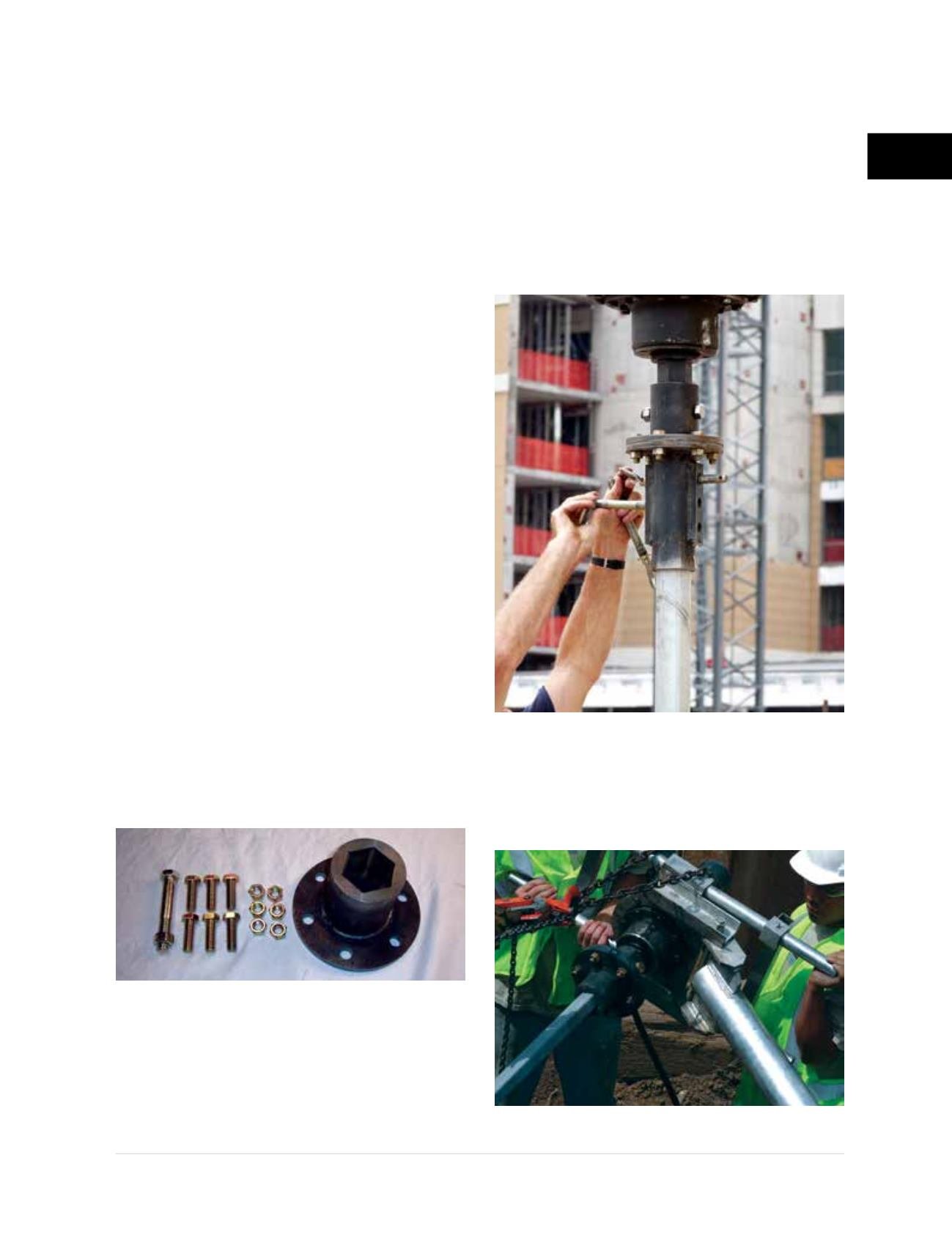
2.12.2.2 Installation Tooling
Installation tooling consists of the components that
are attached in-line between the drive head and the
helical pile, generally a hex adaptor and a product
adaptor. The drive head output shaft is typically a
hexagonal shape with measurements ranging from
2 inches to 3 inches across flats. The hex adaptor
slides over and is pinned to the output shaft of the
drive head
(Figure 2.12.2.2.a)
. The flange plate of the
hex adaptor has abolt holepatternwithhole spacing
and diameters to allow bolting to the appropriate
product adaptor for the dimensions of helical pile
shaft to be installed. Product adaptors are available
for the various sizes of hollow round shaft as well
as for solid square shaft. The ends of round shaft
helical piles generally slide into the product adaptors
and are connected with temporary hitch pins or
bolts for installation
(Figure 2.12.2.2.b)
. Solid-stock
internal product adaptors may also be used for
certain sizes of the round shaft helical product line.
The ends of square shaft helical piles and tiebacks
slide into a square, socket-like product adaptor
(Figure 2.12.2.2.c)
.
Installation tooling may also include an in-line
torque monitoring device as discussed in the
following section.
Figure 2.12.2.2.a
Hex adaptor
Figure 2.12.2.2.b
Round shaft product adaptor
Figure 2.12.2.2.c
Square shaft adaptor