


 15 / 365

© 2014 Foundation Supportworks
®
,
Inc.
All Rights Reserved
p 15
Chapter 2
Helical Foundation Systems
CHAPTER 2
HELICAL FOUNDATION SYSTEMS
However, FSI still recommends that a positive
connection be made so the bracket is not lifted
or floated off the top of the pile during concrete
placement operations. Welding or bolting of the
bracket to the helical pile is required to resist
tension loads.
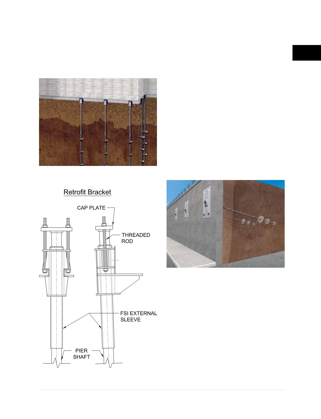
Retrofit brackets are used for
underpinning
existing structures
. These brackets are often
referred to as side-load or “L” brackets and are
typically designed to support the foundation
from below
(Figures 2.3.3.b1 and 2.3.3.b2)
. The
horizontal leg of the “L” is positioned below the
footing or foundation wall while the vertical leg
is positioned against the vertical face of the
footing or foundation wall. Footings that extend
beyond the face of the foundation wall are
typically notched-out at the bracket locations
to create a smooth, flat surface and so the
bracket is positioned as far as practical below
the wall. Helical piers with retrofit brackets are
often used to re-support existing structures that
have undergone settlement. These same retrofit
systems can be used to support additional
loads transferred to an existing structure due
to a building renovation or construction of an
adjacent addition.
Wall stabilization, earth retention, or
embankment stabilization
projects often
utilize helical tiebacks or helical soil nails as
system components
(Figure 2.3.3.c)
. Helical
tiebacks and helical soil nails may consist
of either hollow round shaft or solid square
shaft, although square is more common due
to its socket-and-pin style coupling (quick
connection) and the ability to penetrate further
into the soil with a similar amount of installation
torque than a comparably-sized round shaft.
The end of the shaft is typically fitted with an
adaptor to transition the shaft to threaded rod.
Figure 2.3.3.c
Rendering of helical tieback installation
Figure 2.3.3.b1
Rendering of retrofit helical piers
Figure 2.3.3.b2
Retrofit bracket detail