


 238 / 365

© 2014 Foundation Supportworks
®
,
Inc.
All Rights Reserved
p 238
Chapter 3
Hydraulically-Driven Push Piers
CHAPTER 3
HYDRAULICALLY-DRIVEN PUSH PIERS
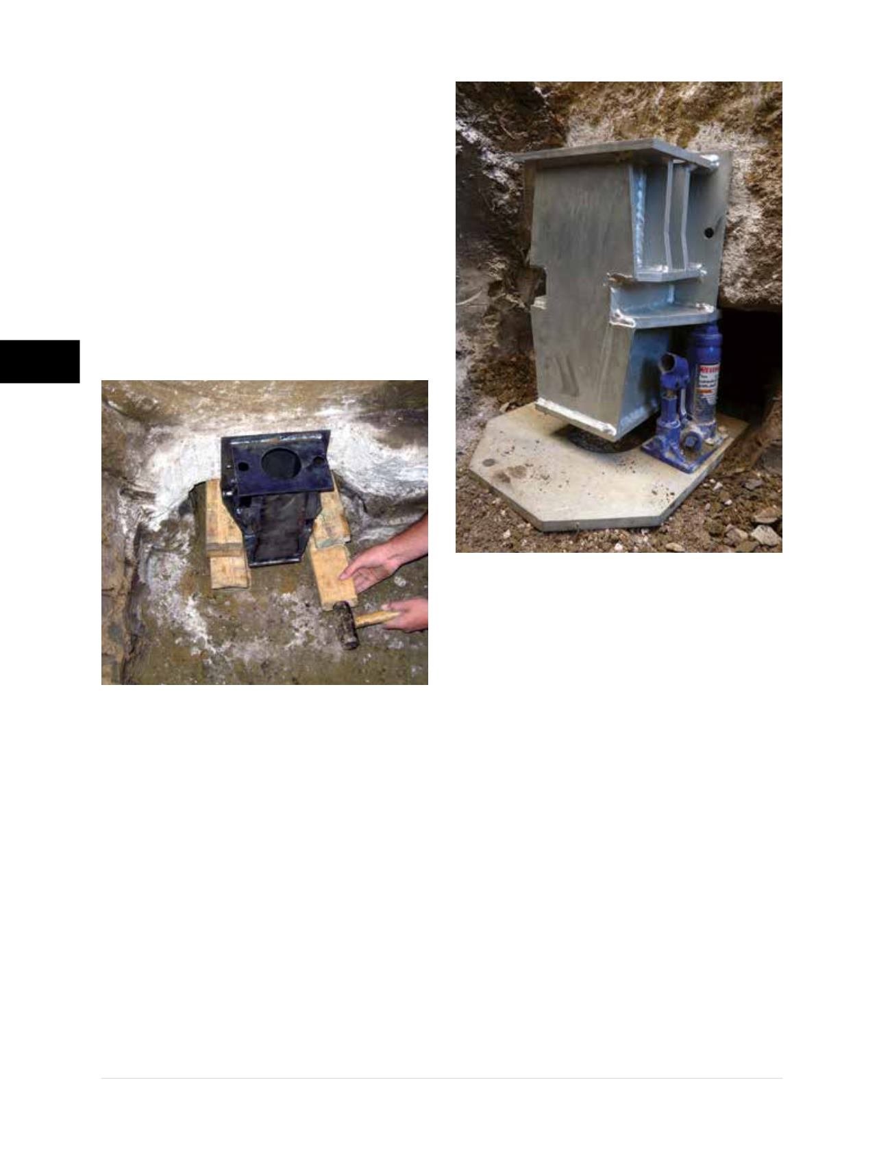
Step 2 Positioning the Bracket
• The bracket is placed under the footing and
raised into position with the horizontal and
vertical bearing plates in full contact with the
concrete surfaces. The bracket is temporarily
held in place using wood cribbing
(Figure
3.10.c1)
. Alternatively, a bracket RAYser
™
is
available from Foundation Supportworks for the
more commonly used brackets. The bracket
RAYser consists simply of a U-shaped plate
with bottle jacks to position the bracket and
hold it snug against the concrete during the
initial pier installation process
(Figure 3.10.c2)
.
Note:
For the Model PP400 system without an
external sleeve, the starter tube with the friction
reduction collar needs to slide up through the
bottom of the bracket before setting the bracket
against the footing.
• FSI under-footing brackets do not require
mechanical anchorage to the concrete
foundation. The published capacities are based
on testing and analyses without anchors. There
are bolt holes that may be used to mount the
bracket to the concrete with expansion or
adhesive anchors, if needed to meet the project
specifications. It should be noted, however, that
the use of anchors to mount the under-footing
bracketmay cause concrete spalling and cracking
from the repeated loading and unloading process
during pier installation and lock-off. Additionally,
drilling the anchor holes could compromise the
integrity of steel reinforcement. If mounting of the
under-footing bracket with anchors is required,
FSI recommends anchoring the bracket after the
system has been locked off.
Step 3 Mounting the Drive Stand and
Hydraulic Drive Cylinder
• Slide the exterior sleeve over the starter tube and
insert the sleeve and starter together through
the bracket
(Figures 3.10.d1 and 3.10.d2)
. Care
must be taken that the sleeve and starter are
properly aligned and extend past both the top
and bottom plates of the bracket. The sleeve
and starter could also be placed after mounting
the drive stand to the bracket. Installers may find
it easier, however, to set the sleeve and starter
without being restricted by the drive stand legs.
Figure 3.10.c1
Temporary bracket support with wood cribbing
Figure 3.10.c2
Bracket RAYser
TM
support system