


 239 / 365

© 2014 Foundation Supportworks
®
,
Inc.
All Rights Reserved
p 239
Chapter 3
Hydraulically-Driven Push Piers
CHAPTER 3
HYDRAULICALLY-DRIVEN PUSH PIERS
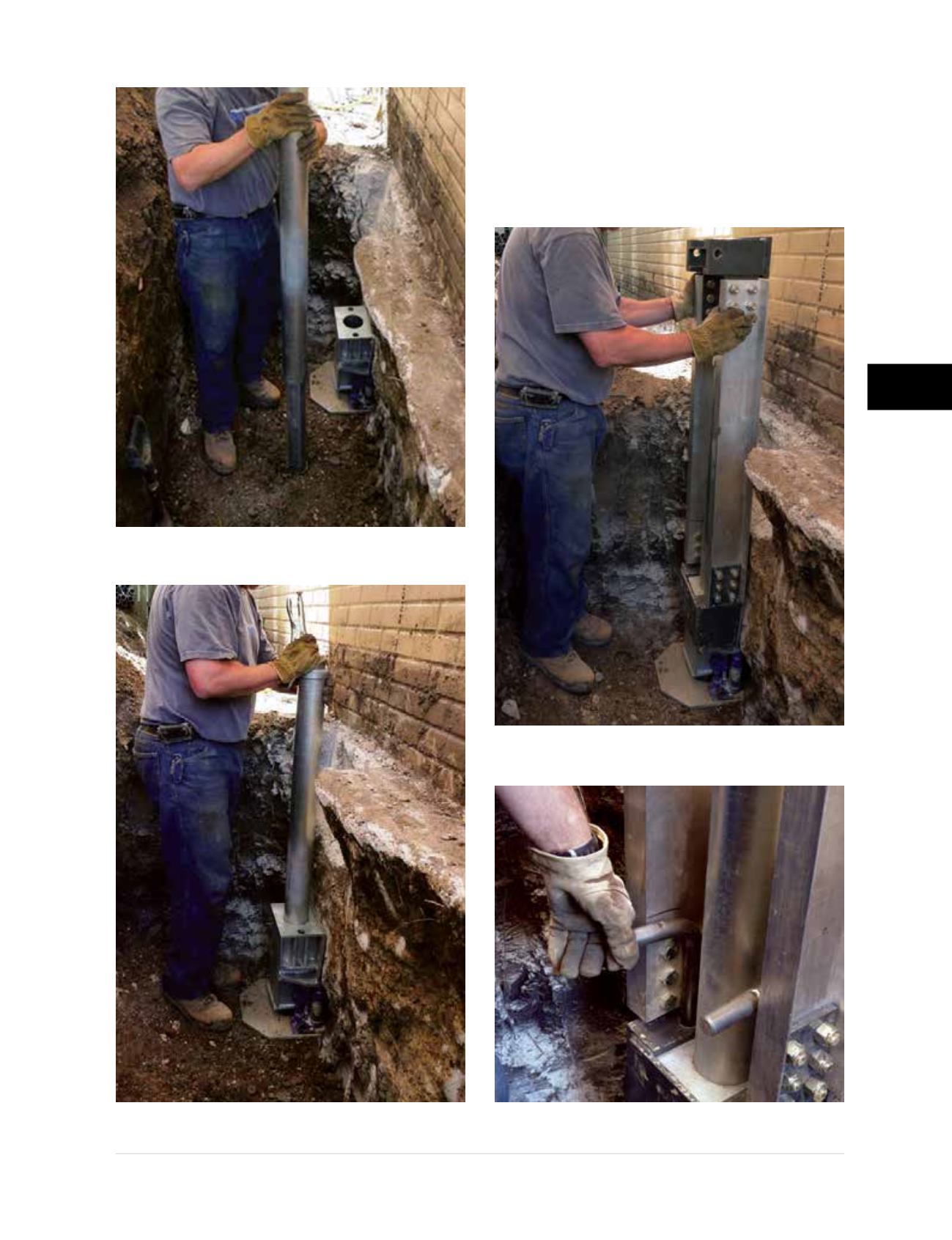
• The drive stand is fitted to the bracket and secured
with coil rod (PP237 system), L-pins (PP288
system) or bolts (PP350 and PP400 systems).
Figures 3.10.e1 and 3.10.e2
show setting of the
drive stand for the PP288 push pier system and
securing it to the bracket with L-pins.
Figure 3.10.d1
Exterior sleeve slid over the starter tube
Figure 3.10.d2
Sleeve and starter
inserted together through the bracket
Figure 3.10.e1
Drive stand for PP288
push pier system fitted to the bracket
Figure 3.10.e2
PP288 drive stand
secured to the bracket with L-pins