


 51 / 365

© 2014 Foundation Supportworks
®
,
Inc.
All Rights Reserved
p 51
Chapter 2
Helical Foundation Systems
CHAPTER 2
HELICAL FOUNDATION SYSTEMS
dial face then provides a reading of torque rather
than pressure. A different differential pressure
gauge is therefore needed for each drive head.
Electronic pressure indicators
measure the
feed and return line pressures with electronic
pressure transducers. Low voltage power is
supplied to the unit by either a portable battery
pack or a direct connection to an appropriate
low voltage source generated by the installation
equipment. Instead of analog gauges, electronic
indicators such as the PT Tracker by Marian
Technologies
(Figure 2.12.2.3.c)
typically have
a digital screen output to provide a direct
reading of torque, which is generated by a pre-
programmed relationship of the pressure drop
across the motor and the GMM for the drive
head being used. Some units have a selector
switch that allows for torque readings with
various motors. Some models also allow for
data acquisition and/or blue tooth technology.
Shear pin torque limiters
are mechanical in-
line devices consisting of two independent plate
assemblies mounted to a central shaft, but allowed
to rotate independently. Each plate has a series of
holes around the perimeter that allow for insertion
of steel pins with a given shear strength. The pins
are placed in the holes of the top plate to extend
past the interface between plates and into the
holes of the bottom plate. The pins bridge across
the interface and restrict the independent rotation
of the plates until sufficient torque is applied. The
pins will theoretically shear simultaneously when
the torque applied exceeds the summed capacity
rating of the pins. For example, if 3,000 ft-lb of
torque is required for a helical pile installation, six
pins rated at 500 ft-lb each would be inserted into
the housing. The pins should shear simultaneously
when 3,000 ft-lb of torque is reached.
Mechanical dial indicators
are in-linemechanical
devices consisting of a torsion bar mounted
between two separate, bolted flange plates. An
in-line dial indicator measures the twist of the
torsion bar and reads torque in units of ft-lb on the
dial gauge. This device can be used to establish a
torque correlation between pressure gauges and
a specific drive head through dynamic testing.
The
shaft twist method
is simply a visual
observation of the shaft deformation or twist that
occurs with square bar helical products
(Figure
2.12.2.3.d)
during installation. With this method,
the installer must know the range of torque
required to initiate plastic deformation in the
shaft for the given product. This method does
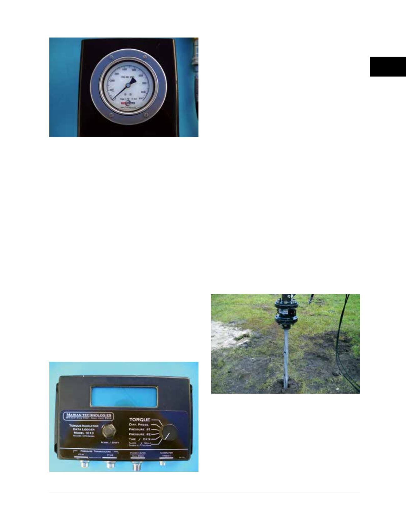
Figure 2.12.2.3.b
Tru Torque gauge
Figure 2.12.2.3.c
PT tracker
Figure 2.12.2.3.d
Shaft twist